6A/3251 / KTD 0701K
Aircraft Tachometer Indicator - Percent RPM
Repair
I was kindly given this indicator, but it was in need of some work as the hands were stuck.
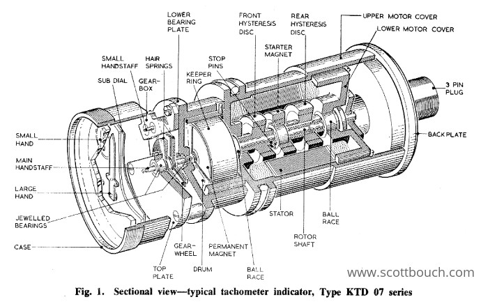
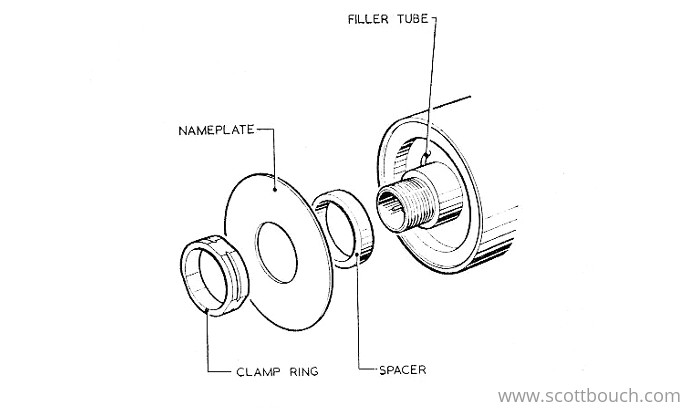
This cutaway drawing from AP-112G-1203 was a great help to give me an idea of what to expect:
Opening it up
1. Remove the nameplate
First task was to remove the nameplate disk, which is held in place by a clamp ring, which is an interferance fit around the 3 pin plug. There is a special extracion tool, which I didn't have, so I went for heating it up and wriggling it off. To get enough heat energy into the ring to release it, I had to use a plumbers blow-torch and pull on it with a pair of pipe grips.
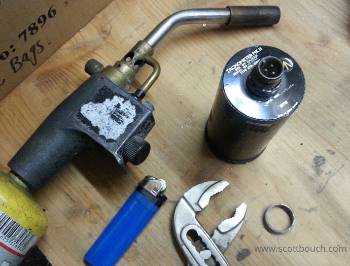
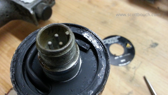
Once the nameplate is off, recover the aluminium spacer from behind.
2. Prepare the case for removal
Scratch away the black paint form the ring of the back plate to expose the solder below.
3. Remove the case
This indicator is held togehter by the back plate being soldered to the case, so again with the indicator in a vice, I used the blow-torch to heat the case and back plate to melt the solder.
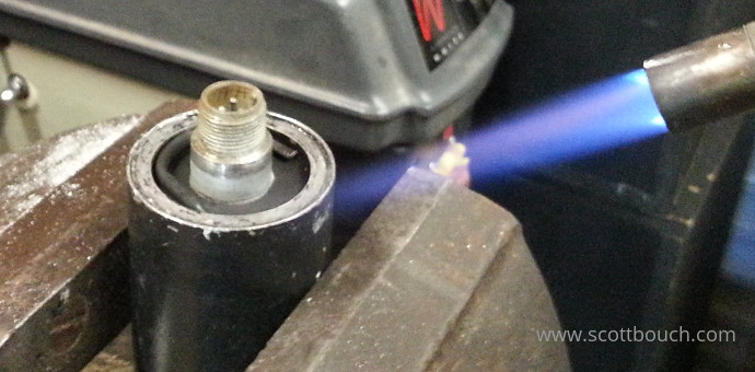
Once the solder was visibly moulten, (keeping the heat on) I used the pipe grips to pull up on the connector to slide the indicator out of the case. This was hindered by an internal O-Ring sliding up the inside of the case, but it eventually came free.
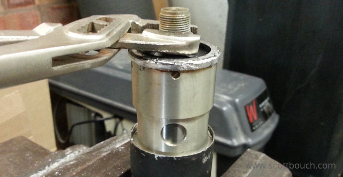
AP112G-1203-16 talks about a special puller, which I didn't have, so I opted for a pipe wrench. It also talks about induction heating the case to melt the solder, or alternatively a massive soldering iron, again I didn't have this equipment, so used the plumbers blow torch.
The AP also recommends severing the flattened end of the tube to release gas pressure; the only reason I didn't do this was becasue this indicator has a cracked glass front, but it would be recommended to save hot solder splattering out with pressure behind it if working on an indicator with no other holes in the case.
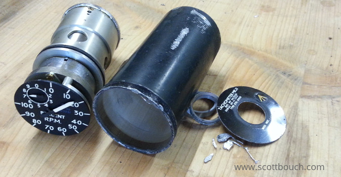
Leave to cool down before attempting the next step.
Removing the upper mechanism from the motor
The upper mechanism (with dial and hands) is clamped to the upper motor case, there is a small dowel for locating it, and a screw that releases the clamp. Loosen this screw and gently ease the mechanism off beaing careful to keep it aligned straingt with the motor, as the copper drum is a close fit around the magnet.
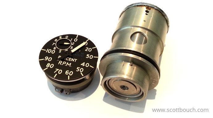
Dismantling the upper mechanism
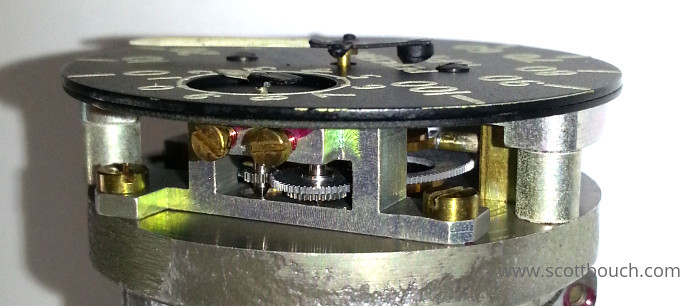
A very beautiful and delicate mechanism, like a clock or wristwatch.. it has jewel bearings, little gears, and tiny hair springs... Quite the other end of the spectrum to the blowtorch used earlier!
1. Removing the hands
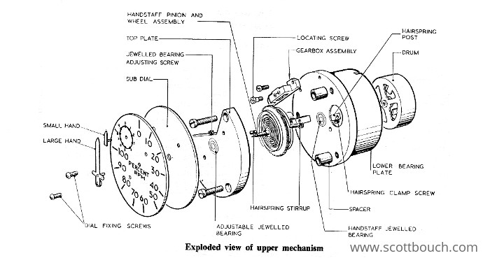
The hands came off relatively easily; they are attached to small tubes bored with a 3 degree taper, which fits onto mating tapers of the two handstaffs. I used two small screwdrivers to gently prise the hands off.
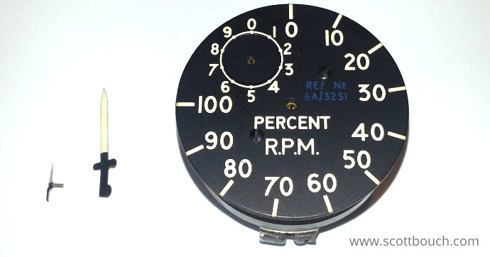
That was the easy bit... the two brass screws holding the dial on are hard to budge, and of course are getting chewed up, so I may end up drilling them out and replacing.
[How it works]
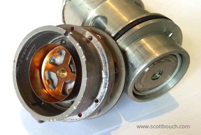
The copper drum is clearly visible (below), which fits snugly around the magnet on the front of a three phase synchronous hysterisis disk motor (synchronous = the motor rotates in sync with the generator, ie: same speed). Together, the magnet and copper drum form the contactless magnetic coupling to move the hands.
As the motor rotatates the magnet, the field induces small eddy currents in the copper drum. These eddy currents set up their own magnetic fields which interact with the main rotating magnetic field, and magnetic attraction causes the drum to be dragged round against the hair springs.
As engine speed changes, so does the frequency of the three phase signal produced by the on-engine tacho generator. Any change in frequency changes the speed of the motor; more speed, and the magnet rotates faster in the copper drum, causing the drum to push harder against the hair springs, movong the hand round the dial.
Investagaing the issue
Once the two halfs were split, it became obvious that the motor could spin freely, but the upper mechanism could move by hand, but it's motion was too stiff for the two hair springs to return it to zero.
It also became obvious that this indicator had been apart before (without the special tools) as there was evidence of screwdriver marks levering the upper mechanism off (photo above). This belief was reinforced, as the hands were not set to zero correctly. So someone else had either tried fixing the issue, and given up; or maybe even caused the issue...
NEXT...
Well, that's the project so far, next hopefully I'll find what's up with it and sort it out..
Thank-You's
I've received some very kind help from people who have found my projects by stumbling across this website and made donations, so to acknowledge their kindness, many thanks go to:
- Mike Davey for giving me the indicator.
- Terry Parker for the AP manual.
