ATtiny85 programming with an
Arduino UNO as an ISP
There are many web pages on programming an ATtiny85 using an Arduino UNO as an ISP (In-System Programmer), but most of them don't quite fully / thoroughly describe the hardware connections between the two, so I thought I'd share this information in a more concise manner.
As most other posts show breadboard (☠) and flailing wires, I thought I would share my Veroboard / stripboard layout for this programmer.
All of the ATtiny85 pin connections are as such:
| ATtiny85 | UNO |
|---|---|
| pin: | pin: |
| 1 | RESET |
| 2 | N/C |
| 3 | N/C |
| 4 | GND |
| 5 | 11 |
| 6 | 12 |
| 7 | 13 |
| 8 | VCC |
I won't be covering the software side as it is already well documented over on Arduino's own website and there is no point in duplication. See: arduino.cc, I will be following this guide later to program it.
Design
The circuit diagram:
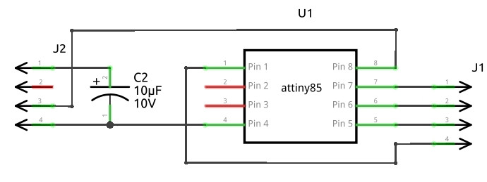
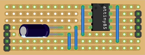
And here is the Veroboard / stripboard layout on a 20 x 7 piece.
NOTE: all 4 tracks under the ATtiny85 are cut in addition to the cuts that you can see:
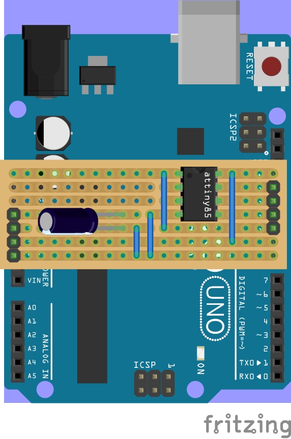
And this is how the assembled programmer should look when mounted on an Arduino UNO board:
Please feel free to download the fritzing file, I have also roughly laid out a PCB too within the file:

Build
This is using a non-official "Arduino UNO" copy, as I recently blew up my official one.
I get frustrated when reading other hobbyist blog posts describing a circuit or software idea, without actually building it or trying it out, so you have no idea if the other person's ideas actually work or not, and then invest hours in a road to nowhere.
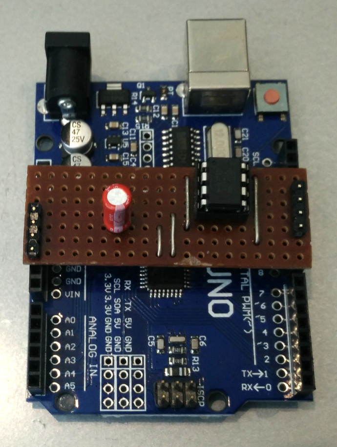
So, here is the actual board to show I actually did make it:
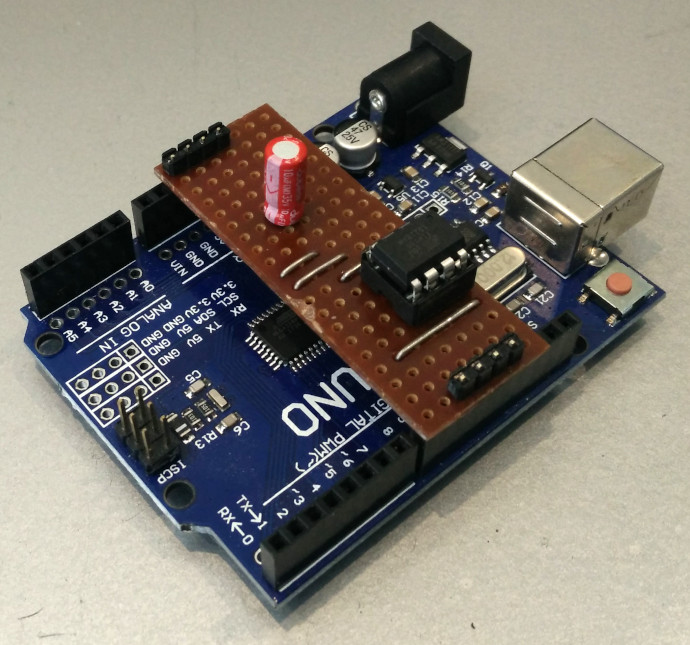
Notice how as the components are mounted on the top of the board, and the header connectors are on the bottom (a bug-bear I have with Arduino's choice of connector, making single sided PCB projects a bit impractical), I had to push the header pins through the plastic supports and solder on the underside in order for them to be long enough to reach the Arduino contacts.
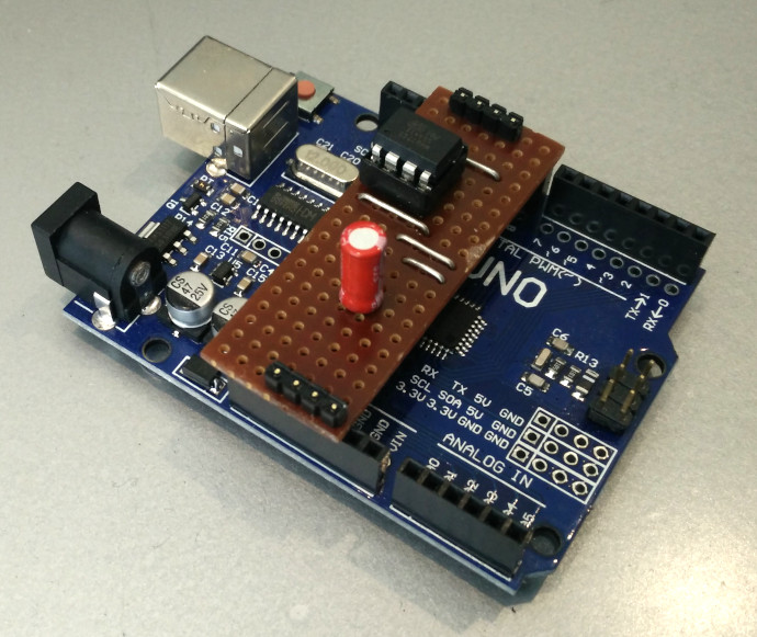
The other issue with Arduino header layouts is that the header sockets on each side don't exactly align with each other! For this little board it's not a problem as it can fit at a slight angle. If you were etching a PCB, you could compensate for the misalignment, but it makes life hard with Veroboard / stripboard spanning both sides.
Test
I followed the official guide for programming the ATtiny85 at arduino.cc, which has a few steps, but is not too tricky.
To my amazement, I didn't blow up either the Arduino UNO or the ATtiny85, instead, it worked like a charm! I modified the "blink" program to control two LEDs independently, and was delighted to see it working.
Conclusion
After building this little board and trying it out, I can assure you that it works! Have fun having a go yourself!