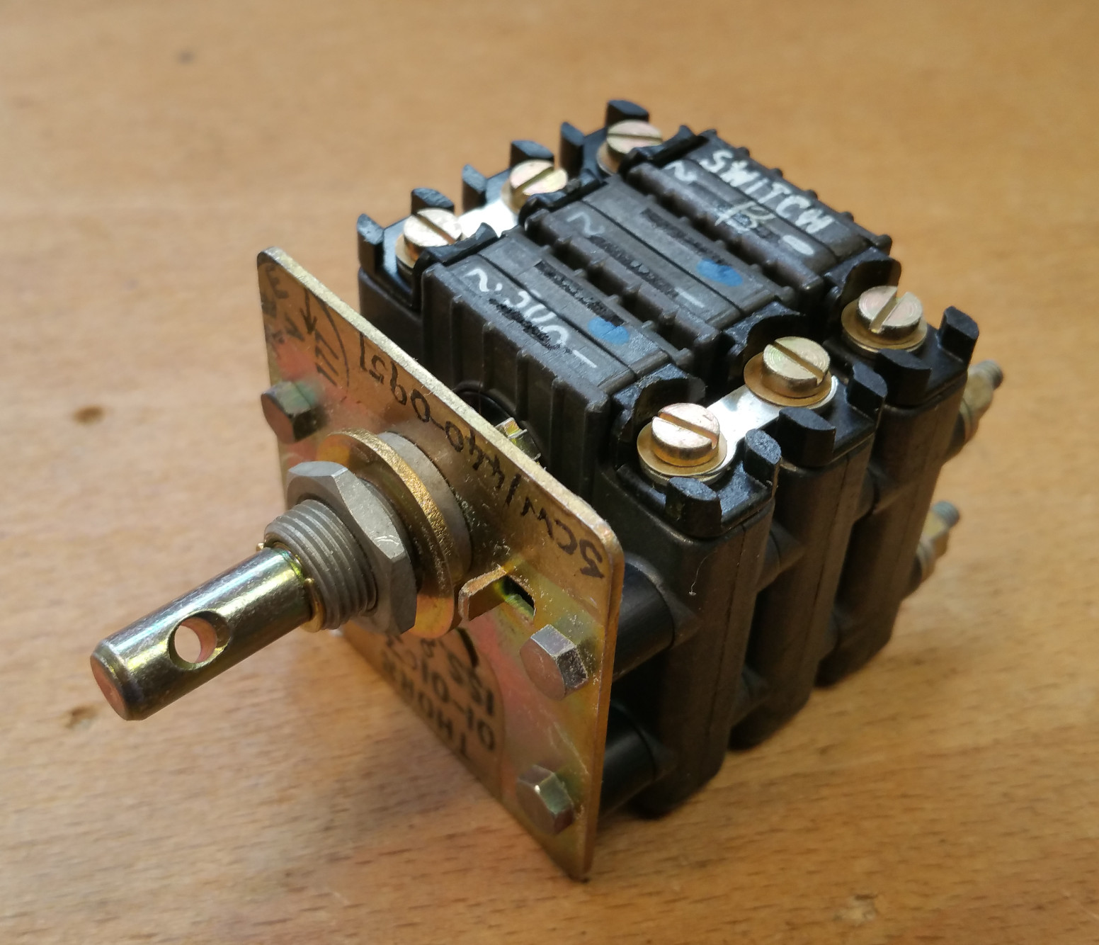
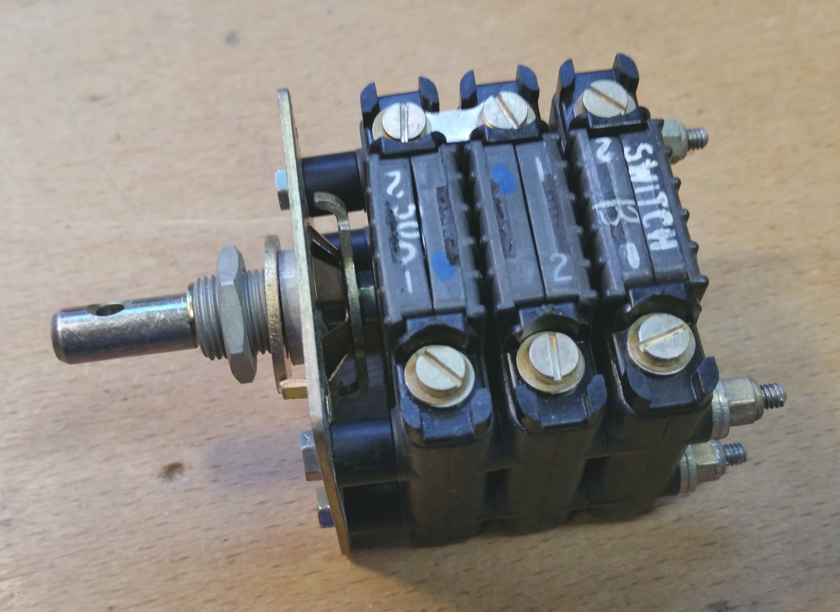
Thorn dimmer switch
A modular dimmer switch assembly, suitable for low power panel lighting. Its modular design means that many configurations are possible by stacking up rheostats. Each configuration has its own Thorn part number and stores reference number, so are not intended for swapping and changing in service to suit needs, but Thorn would make up custom dimmer switches to order.
Four bolts made to the correct length pass through all items of the stack and clamp the stack together to the front plate. Shaft rotation is 90 ° with firm end stops. A friction system keeps the shaft in position during flight.
Where a single dimmer switch is required to dim numerous lamps, multiple rheostats can be stacked up on a longer shaft, and connected in any arrangement as needed (such as in parallel pairs), or individually. Dimmer Sections
The rheostats have a purposeful open-circuit section at the very lowest setting, just for the last few degrees of shaft rotation, thus ensuring no current flows to the lighting circuits when fully dimmed.
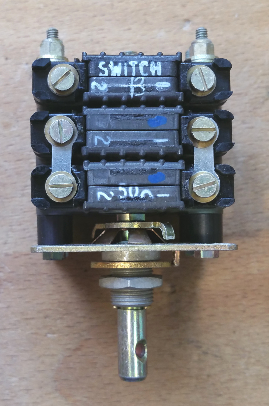
Added to the end of the stack, it is common to see a switch. This switch will open when at the last few degrees of shaft travel, and is closed at any other shaft angle. The Lightning uses this switch to provide just two brightness levels to the warning lamps.
| Stores Ref. No.: | 5CW/440-0951 |
| Manufacturer: | Thorn |
| Manufacturer P.N.: | 01-0103-37 Iss.8 |
| Connection: | Screw terminals |
| Attachment: | Nut |
Comprised of two 100 Ω resistors connected in parallel, the painted 50 Ω marking refers to the unit as a whole, not the individual dimmer sections.
Thorn dimmer switch
Electrical connections
As rheostats only have two connections (one end of the resistive element, and the wiper) it is hard to utilise with an analogue input of a microprocessor, which will expect to see a variable DC voltage between 0V and either 5V or 3.3V depending on the Arduino processor type.
A way to provide this is to use an external resistor from a positive supply, connect it to the "top" of the resistive element, and connect the wiper to 0 V. By observing the voltage across the rheostat a measurement can be taken.
However, this has a drawback in that it is impossible to make full use of the whole 0 V to 5 V range, so input resolution is limited.
A higher voltage power supply could be used to utilise the full input resolution, but this carries the risk of damaging the microprocessor input if there was a break in the circuit on the 0V side.
With a slight alteration to the stack, the two rheostats can be made to act as a potentiometer, allowing the Arduino analogue input to observe a smooth progression from 0 V up to the positive supply voltage.
This alteration is not permanent, and is easily reverted back, so I am happy to implement it without upsetting my preservation ethics.
This trick is clever, as it's so simple. It is made possible by virtue of the shaft having a 90 ° rotation (any greater than 180 °, would not have worked), and the centre point of the resistance being aligned with the centre of travel.
Where a dimmer uses two rheostats in parallel, simply flip one around so it's working in reverse, and only re-connect one side using the linkage, this connection represents the wiper of a potentiometer, and the other two connections are for 0V and a positive supply.
As the shaft turns, the resistance of one rheostat increases, while the resistance of the other rheostat falls, shifting the common connection point fully between the supply rails, acting exactly as a potentiometer does, and utilising 100 % of the Arduino input resolution for highest accuracy.
The downside is the current drawn. While this change will double the pair's resistance, eg: 50 Ω becomes 100 Ω over all, but this is still a low resistance. The on-board regulators of Arduino's and similar I/O boards have a limited current available for input potentiometers and the like, so care has to be taken not to exceed this, or use an external LDO voltage regulator to supply the dimmers.
An example is a 5V supply to a now 100 Ω dimmer, will result in 50mA being drawn from the regulator. However, this is lessened, as when the wiper reaches the end of the resistive element, (as mentioned above) it goes open circuit, now with one rheostat flipped around, the current is not drawn when fully clockwise or anti-clockwise as there are now two open-circuit positions at each end of travel.
Re-assembly of a rheostat pair, resulting in a 100 Ω potentiometer configuration, using Solution No. 2. at 5 V supply, the 100 100 Ω resistance will draw 50 mA from the regulator.
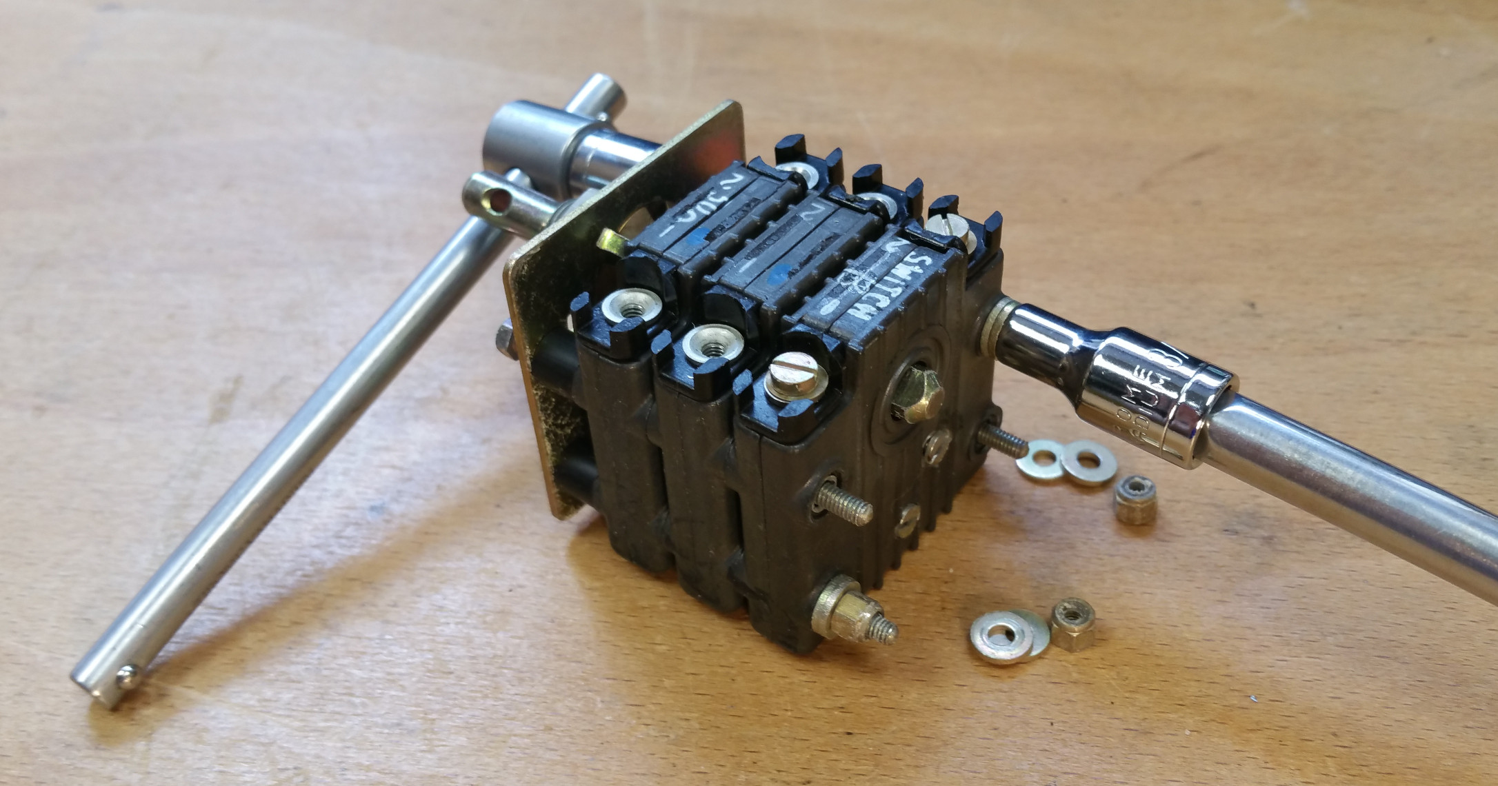
Dismantling Thorn dimmer switch
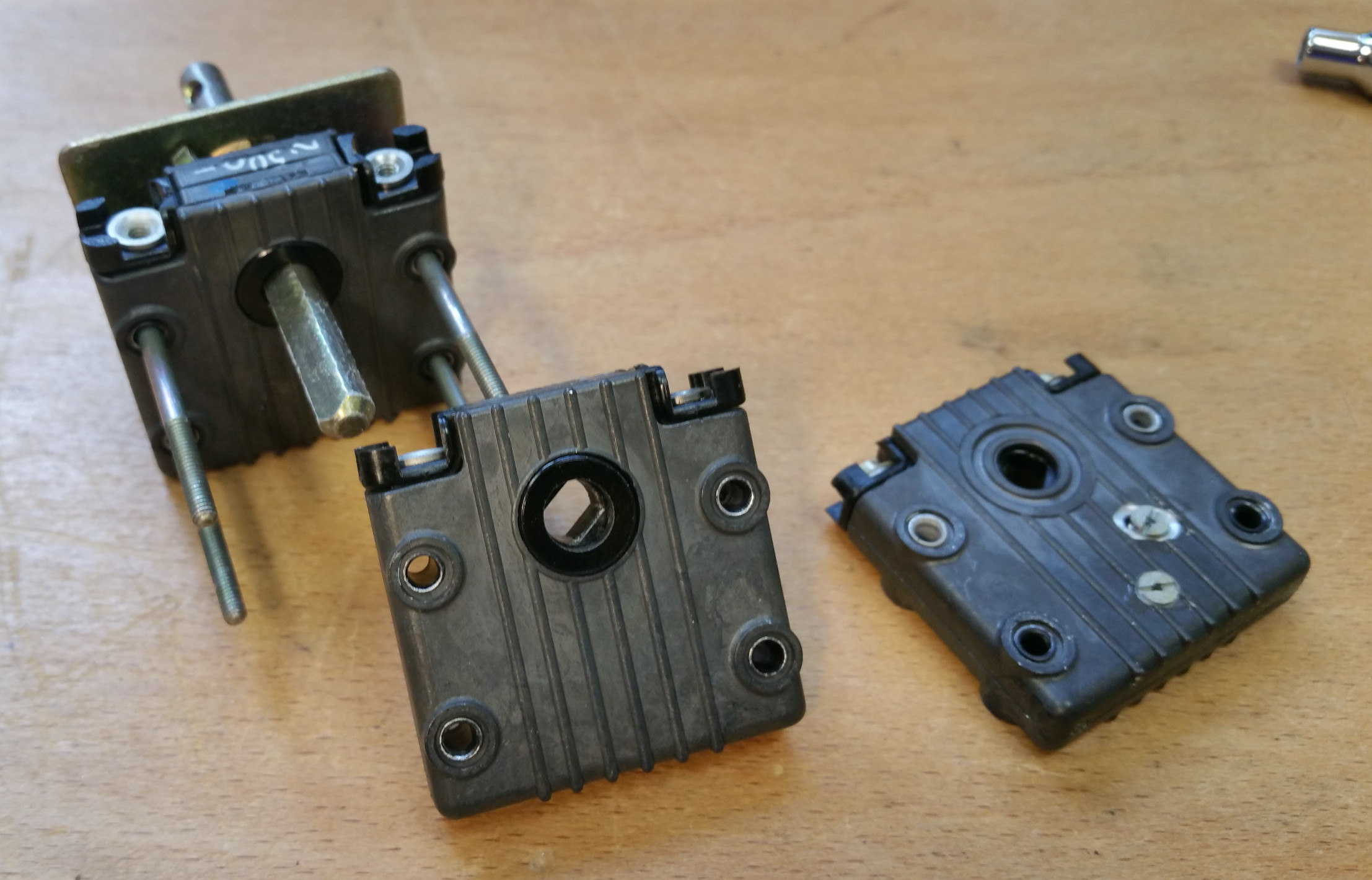
Dismantled Thorn dimmer switch
Once dismantled, the keyed rotor in the removed rheostat needs rotating through 90 °, so that when the unit is turned around it will align with the shaft again for rebuilding.
Re-assembled Thorn dimmer switch with second rheostat reversed (note the terminal numbers)
One way to reduce the current drawn by a dimmer, is to use a longer version with multiple rheostat pairs, such as the example below where two pairs have been configured for testing. In this example the white wires are the power supply 0V and positive, and the orange is the "wiper". The result here is 200 Ω, 25 mA at 5 V.
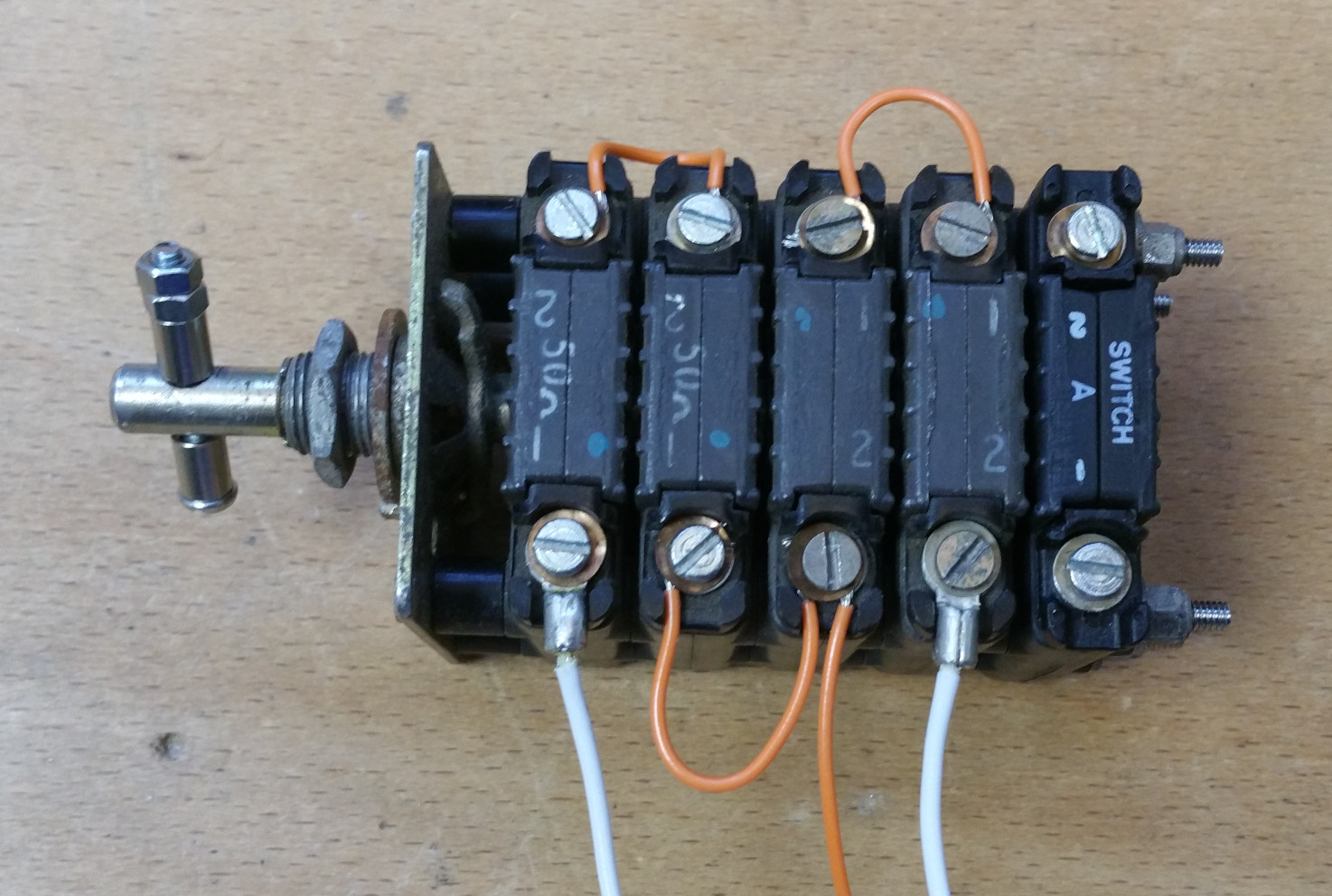
Thorn dimmer switch with two rheostats reversed (note terminal numbers)
There are two potential downsides to this arrangement, there are 4x wipers, so 4x the chances of a dirty contact causing an intermittent connection, and a stack of 4x rheostats plus a switch is mechanically quite hard to rotate.

Thorn advert - Miniature Dimmer Resistor
Published: Flight, 18th April 1958
Source: Aviation Ancestry

Thorn advert - Components in the Lightning
Published: Aeroplane, 13th July 1961
Source: Aviation Ancestry
Thorn Manual:
Thorn, 33-10-13, Overhaul Manual, Minature Dimmer Resistors, 31 May 1965