CONTROL UNIT (EXT. RECEIVER) Z
or E/F-BAND HOMER CONTROL UNIT
or S-BAND HOMER CONTROL UNIT
LEADING PARTICULARS
| Stores Ref. No.: | 10L/9134926 |
| NATO Stock No.: | 5895-99-913-4926 |
| Manufacturer: | Ferranti |
| Connection: | 602 Pattern 16-30P |
| Attachment: | Screws |
DESCRIPTION
This radar receiver system provides facility to locate the source of an airborne radar jamming signal in the S-band (or E/F-band). This system works in receive only, no radar transmission is used.
A confusing name: the "Control Unit (Ext. Rec.) Z", is indeed a control unit for an external receiver of the radar system. This receiver looks for jamming radio signals transmitted by a target aircraft and provides facility for homing to this target. These signals are in the range of 1.55 to 3.9 GHz, this range was named "S-band" in cold war era NATO nomenclature, but at some point NATO re-organised their naming structure; the "S-band" was split into two bands named "E-band" (2 GHz to 3 GHz) and "F-band" (3 GHz to 4 GHz), which is why this unit has so many names.
Note: This is not to be confused with the IEEE S-band nomenclature, which is different again.

When switched on, the external receiver provides a blanking signal to the AI receiver, clearing the bottom half of the B-scope display, making space for the external receiver displayed signal.

BAC Warton Lightning T5 Pilot's Notes, 1964, Part 1, Chapter 15, Page 10, C.R.T Display, S-band homing
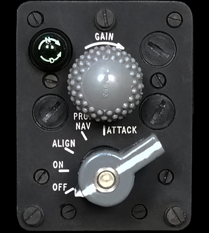
The display resembles noise "grass" along the bottom of the display with a spike, the spike represents the bearing of the jamming signal, by keeping the spike central in the display, the aircraft will be flown toward the target. Approaching the target, the spike will rise above the noise signature (better signal to noise ratio), so the "GAIN" knob of the control unit can be used to reduce the receiver gain, reducing the noise, while keeping the spike visible.
It's distinctive nobbly knob (Part No: 0112993) is manufacturered by Whiteley.
SIMULATION
The main challenge posed by interfacing this unit is finding the correct connector. Aside from that, the unit contains only switches and lamps, so an interface will be straightforward.

Looking inside the rear, only switches and lamps are used, making this a straightforward interface.
However, to make use of this unit in the Lightning model, a lot of work needs to be done to fully understand how this unit works and how the receiver's results are displayed, and to write the software to reproduce what happens in reality.
WANTED
As mentioned above, having the right connector for this unit would make interfacing a lot easier.
The fixed plug on the chassis is a "602 pattern" connector (MIL-C-26482), made by Thorn, which would make this one of their "Pygmy" range. The contact layout has one pin of a larger rating (size 16) than the 29 others (size 20).

Connector needed for interfacing.
It is marked as an 18-30P; the 18 being 18 16ths of an inch in diameter, and the 30 is the contact count, the P means Pins (instead of S for Socket), no further identification letters indicates a normal orientation. Interesting to note that the insert is made by Bendix.
So, I am after a mating free socket, which would be marked 18-30S, of standard orientation.
REFERENCES
T Mk.5 electrical "Vol 1":
AP101B-1005-1B, Section 9, Chapter 3, A.L.73, February 1977, AI 23C - Paragraph 11
T Mk. 5 wiring diagrams:
AP101B-1005-10, Sheet 37, A.L.3, Nov 1981, Cabin Lighting, Starboard