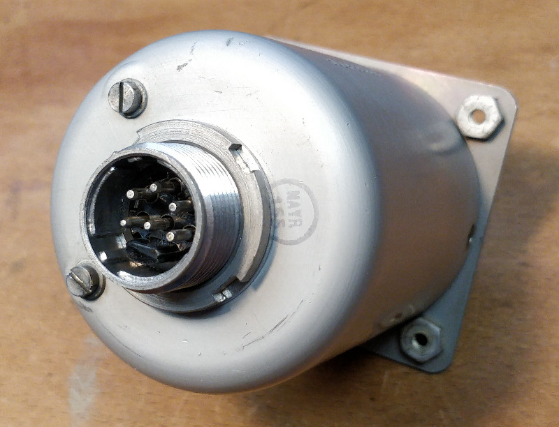
SELECTOR, CABIN TEMPERATURE CONTROL, TYPE FHK/A/22
LEADING PARTICULARS
| Stores Ref. No.: | 5CZ/5404, later 5CZ/4335638 |
| Manufacturer: | Teddington Controls, later Normalair |
| Manufacturer Type: | FHK/A/22 |
| Connection: | Plessey Mk. 4, fixed unit, plug, small shell, 6-way, orientation 0 |
| Attachment: | 28D/1213896 | AS.3295/2B | Bolt, 4 BA, Phillips recess, 90° c'sk head |
DESCRIPTION
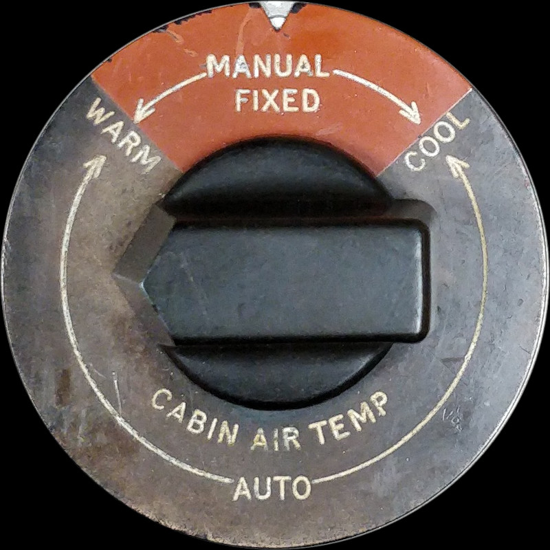
This selector is used to control the temperature of the cabin air. This is achieved by setting the position of the cabin air mixer valve actuator, and resultant ratio of cold and hot air mix being supplied to the cabin.
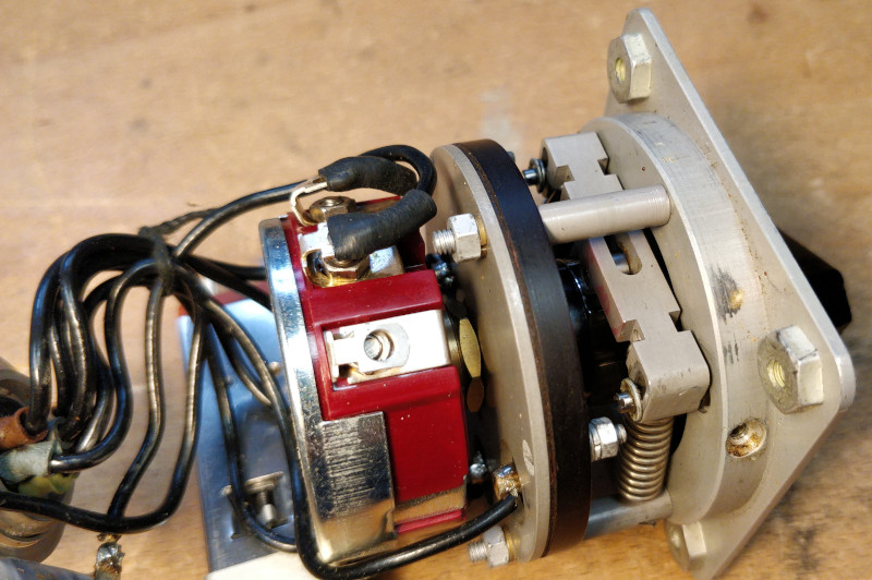
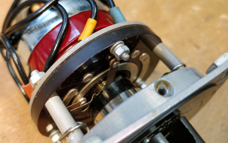
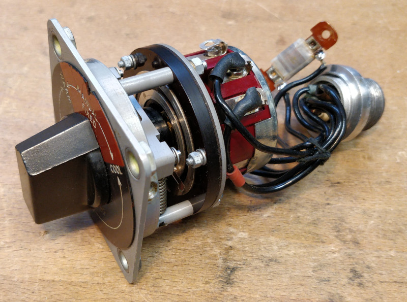
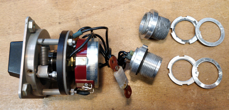
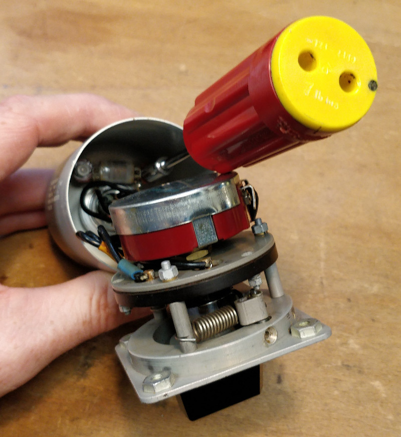
In the above image, left to right are: Potentiometer (red/silver), special rotary switch (black plate), mechanical spring detent system attached to the front plate.
In "Auto" mode the potentiometer is used for automatic control of the cabin temperature: a magnetic amplifier compares the position of this potentiometer against a measured cabin temperature, and operates "increase" and "decrease" relays to position the mixer valve actuator to maintain the cabin temperature constant.
If the automatic mode was to fail, manual adjustment of the actuator can be made using the rotary switch to directly control the "increase" and "decrease" relays to manually set the mixer valve actuator position. In "Manual" mode, the actuator is moved while the aircrew holds the selector knob against its spring, and the system does not automatically react to changes in cabin temperature.
REPAIR
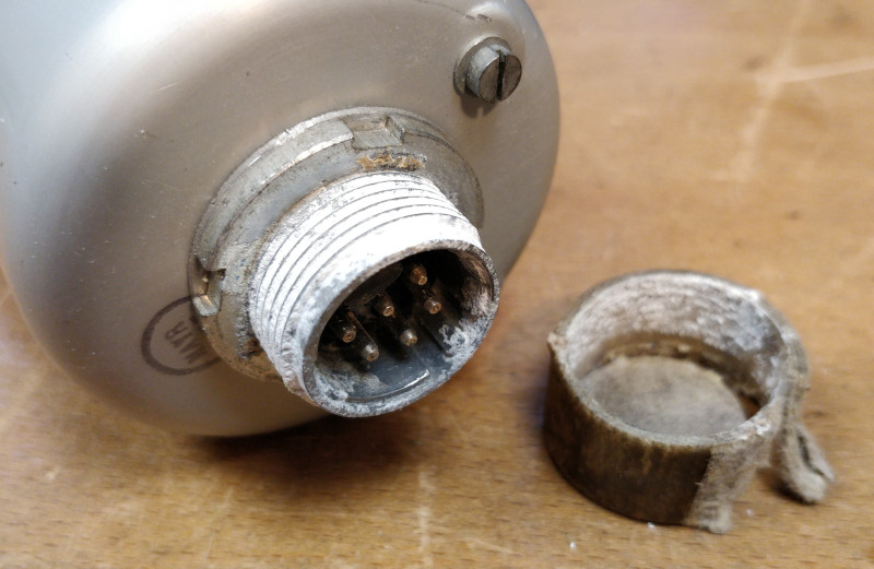
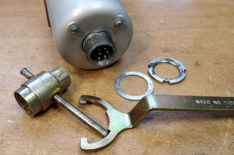
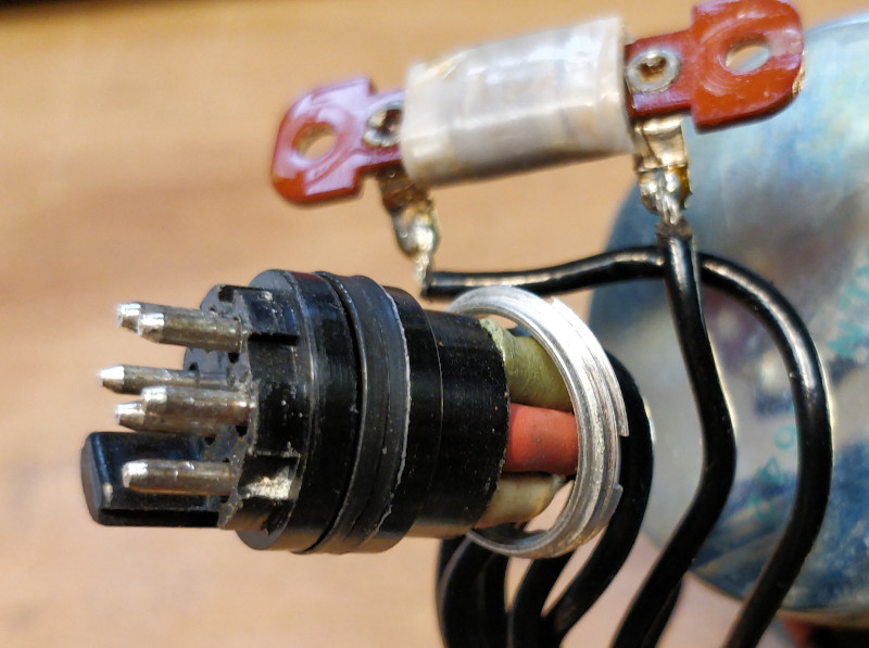
This unit had been in storage for decades with a cardboard protective cap fitted over the Mk. 4 connector. Unfortunately this acted to trap moisture, and caused a significant amount of corrosion to the threads of the connector shell. The best solution was to replace the shell of the connector with a new part, but this required a lot of work to remove the nut of the corroded part.
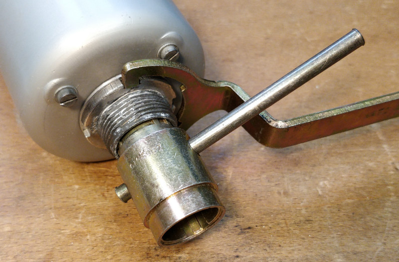
I had to cut the cardboard cap away as it had bonded to the corrosion. Using a fine screwdriver, knife, and brass wire brush most of the corrosion was removed. I then applied a little "PlusGas" release agent, followed by "WD-40" into the threads of the nut. Using the correct tools, and a lot of effort, I was able to slowly remove the nut, little by little.
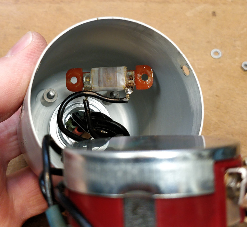
The casing was then removed by removing the three countersunk screws, and releasing the resistor from its mounting adjacent to the connector.
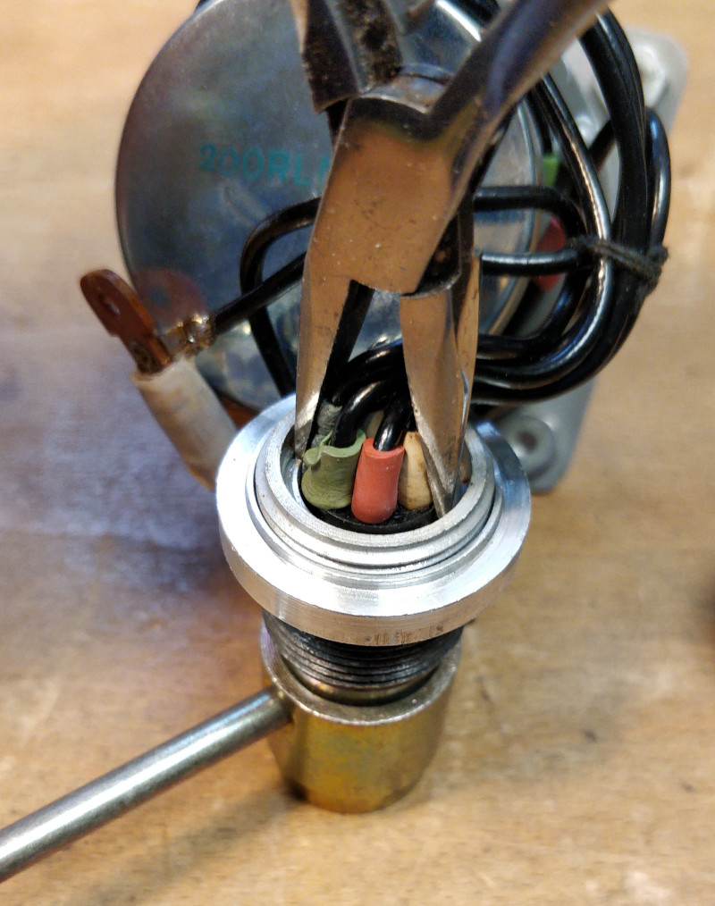
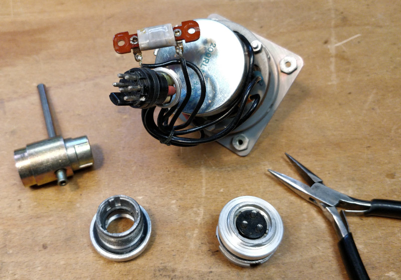
The insulator retaining ring was unscrewed to release the insulator and contacts from the corroded shell, without disturbing the original soldered wire connections to the contacts.
I stole the replacement shell from a new old stock spare 3 way plug.
After some light cleaning of parts and contacts, the connector was re-assembled with the new Mk. 4 shell.
Re-assembly of the unit was straightforward, aside from mounting the resistor to stand-off pillars deep inside the casing, with short wires keeping the potentiometer/switch assembly in the way. But this was facilitated using fine nose pliers to place the standoff spacers, resistor, washers and spring washers in place, then using a 6 BA "Soltork" torque driver to add the nuts.
SIMULATION
This control unit has no direct tangible effect on a simulator unless air blowers and heaters are to be fitted. However, it can be used to control the on-screen representation of itself, and also electrically interact with the simulated relevant circuits.
REFERENCES
T Mk.5 electrical "Vol 1":
AP101b-1005-1b, Sect. 6, Chap. 6, AL59, Sept. 1973, Heating, De-Icing, Rain Dispersal, Air Conditioning - Paragraphs 48 - 50
T Mk. 5 wiring diagrams:
AP101b-1005-10, Sheet 25, Fig. 9, AL3, Nov. 1981, Heating, De-Icing, Rain Dispersal, Air Conditioning - Fig. 4, Cabin temperature control
Teddington Controls literature:
T.C.P. 626 Temperature Controller FLM Types
