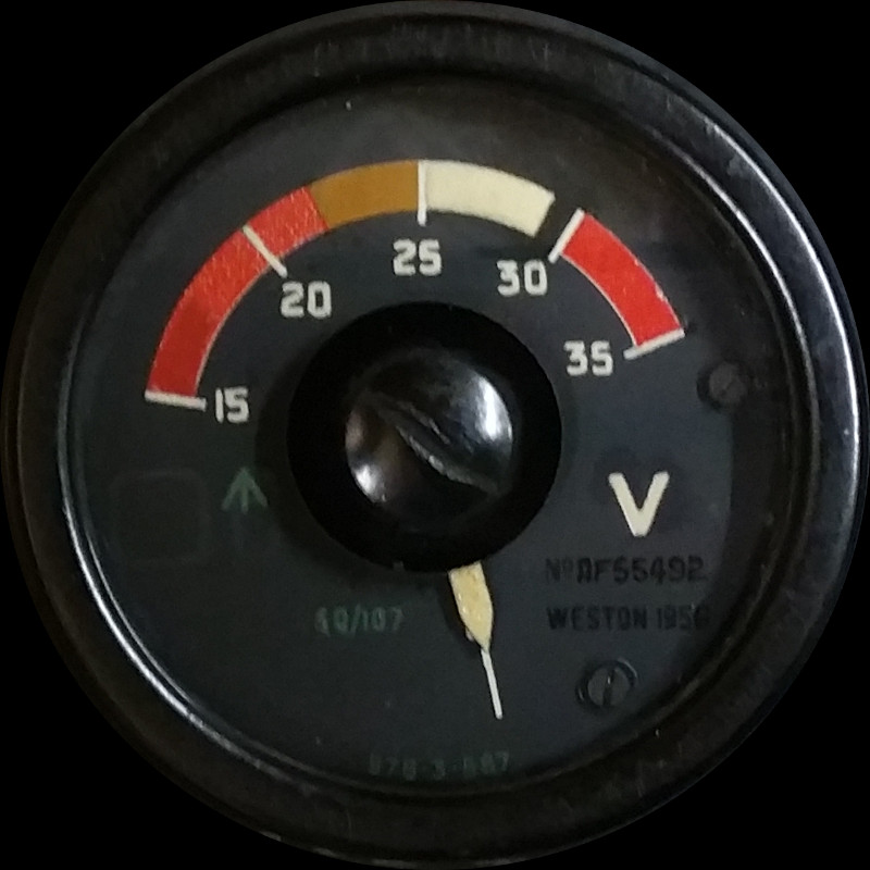
VOLTMETER TYPE S78.3.587
LEADING PARTICULARS
| Stores Ref. No.: | 5Q/107 (later 5Q/4347724 and 5Q/4347726) |
| Manufacturer: | Sangamo Weston |
| Attachment: | 28D/1213896 | AS.3295/2B | Bolt, 4 BA phillips recess, 90° csk |
| Connection: | Screw terminals |
| System: | Electrical Distribution |
DESCRIPTION
DC voltmeter to indicate the voltage of main DC distribution busbar, circuit ID: 'PL'.
It was fitted to all Mk's of Lightning, however the T5 and T55 were fitted with two, one on panel A1, the other on panel A2-ext.
The voltmeter(s) will read around 24V or less when just the battery is connected to the bus bar, an when either external power is connected or the main generator is online, it will read about 28V.
REPAIR
The glass front of one of the two voltmeters had been pushed inward and was loose. This had bent the pointer so that it was rubbing on the face, and also bent the zeroing adjuster arm, causing it to clash with balance arms. Both of these issues restricted the pointer movement.
The image below shows the zero adjuster arm soldered to the end of the clockspring, this arm was bent down, and clashing with the balance arms and twisting the clockspring. The balance arms are visible with wire wrap which is added/removed as needed to balance the mechanism. The pointer is also shown with a gap to the face, after being bent back away from it.

Voltmeter internal movement
The front jewelled bearing sits in the centre of the clockspring, mounted to the centre of the zero adjuster, thankfully this is not showing signs of damage, and the movement moves freely.
This video shows the voltmeter being tested after I straightened out the bent metalwork:
The old Bostik 772 cement was scraped away from the Bakelite case, and remains cleaned off with IPA. As no modern equivalent of the discontinued Bostik 772 could be sourced, the rebuild of the glass and retaining ring was completed using household Evostik.
SIMULATION
Busbar PL is energised if:
- Battery Master switch is on, connecting the battery busbar PE to busbar PL via the battery isolating relay.
- External power is connected supplying to busbar PL via the ground supply relay.
- Main DC generator is in operation and connected to busbar PL via the main contactor.
- Standby DC generator is in operation and connected to busbar PL via the standby generator contactor.
It would be nice to show the battery voltage drop and recover when DC loads are switched on/off but so far I have only modelled the voltages of the DC electrical system, not yet the currents.
This test video shows the genuine performance of the indicator as 28V is applied and removed as a step change, the pointer overshoots and settles down, exactly as it does in the real Lightning aircraft.
REFERENCES
Sangamo Weston Manual:
Electrical Instruments For Aircraft, Section 0 - Prelim
Electrical Instruments For Aircraft, Section 1 - Voltmeters and Ammeters
T Mk.5 electrical "Vol. 1":
A.P.101B-1005-1B, Sect 6, Chap 9, A.L.49, July 1971 - DC power supplies - Paragraph 29