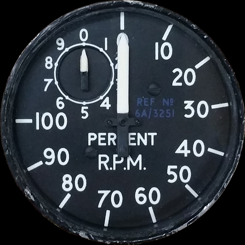
ENGINE TACHOMETER MK.11, TYPE KTD. 0701K
LEADING PARTICULARS
| Stores Ref. No.: | 6A/3251 |
| Manufacturers: | SMITHS and Elliott |
| Attachment: | Clamp, instrument securing type C.12956 |
| Connection: | UK-AN / MIL-C-5015, 3 way |
DESCRIPTION
The tachometer contains a 3 phase synchronous motor, normally driven directly by a three phase tachometer generator fitted to the engine, the speed of which (and frequency of produced signals) depends on engine speed (N1).
They require a 3 phase signal at roughly 26Vac RMS. 4.2 kHz should equate to 100% RPM, equivalnt to maximum N1 engine speed.
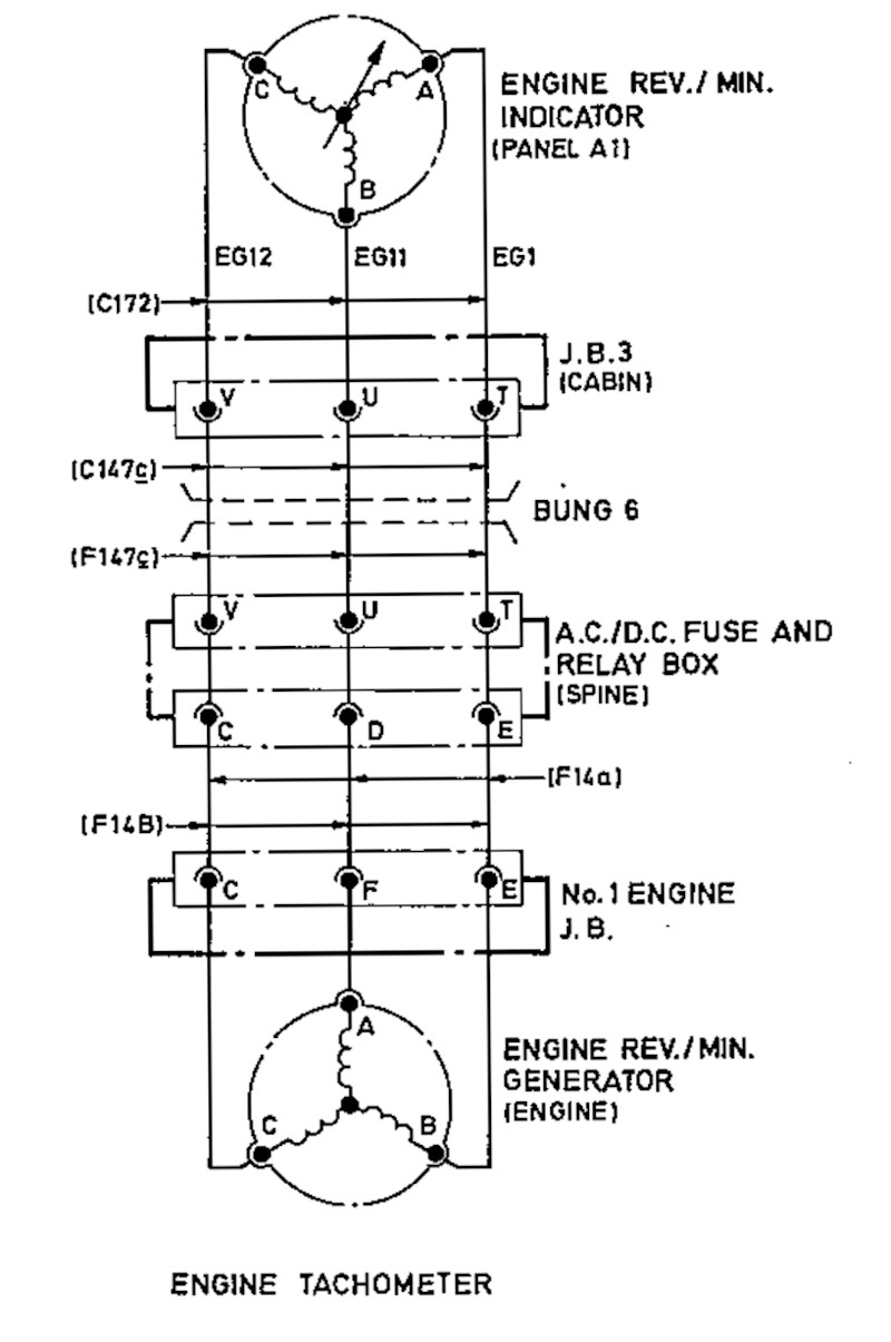
CIRCUIT DIAGRAM
No.1 engine tachometer and generator circuit taken from the T Mk.5 aircraft wiring diagram AP110B-1005-10, Sheet 35, Fig 1, A.L.3, Nov 1981.
SIMULATION
Experiment No. 1
My first attempt at a solid state drive in 2019 consisted of a triple half-H-bridge circuit built with PNP and NPN complimentary pair transistors, and and Arduino UNO to drive them. I wrote a program to sequence the arduino outputs to operate the transistors resulting in a 3 phase variable speed drive (VSD). The video below shows it being limited to 30-40% RPM as I had an exponential error in the code which made the step changes too great for the motor to successfully handle at higher RPM's.
Experiment No. 2
I then in 2020 developed a MOSFET based driver board, which sadly resulted in a cloud of smoke, so clearly my MOSFET design skills need working on!
Experiment No. 3
Late 2021 I was given the idea from someone working on a Bccaneer simulator project to try to use an all-in-one IC to drive these indicators. The IC was a BD63242EFV, which had the potential to be a real winner, as it generates the three phases as full sine waves (high frequency PWM) and has a push-pull triple half H-Bridge output stage that can operate in the right ball park for these motors. The best bit is the motor speed is set by an analogue voltage input (or even raw PWM).
I was very hopeful as my prototype spun up the motor in the indicator, during its initial rotation test, but then fell over. It failed because it was looking for back-EMF generated by a spinning magnet as you would see in a BLDC motor, this motor just uses aluminium disks and eddy currents to drag it around, so no back-EMF, and no hope of using this IC.
I dropped the manufacturer a message to ask if they had any "dumb" versions of these IC's that didn't care about speed feedback, but sadly the answer was no. A great shame as this would have been a really neat solution.
REFERENCES
Indicator general and technical information:
AP112G-1203-16, Chapter 1-1, AL1 May 1966 - Tachometer KTD-0701 K
T Mk.5 electrical "Vol. 1":
AP101B-1005-1B, Section 7, Chapter 4, A.L.51, Nov. 1972, Engine Instruments - Paragraph 23
T Mk.5 wiring diagrams:
AP110B-1005-10, Sheet 35, Fig 1, A.L.3, Nov 1981