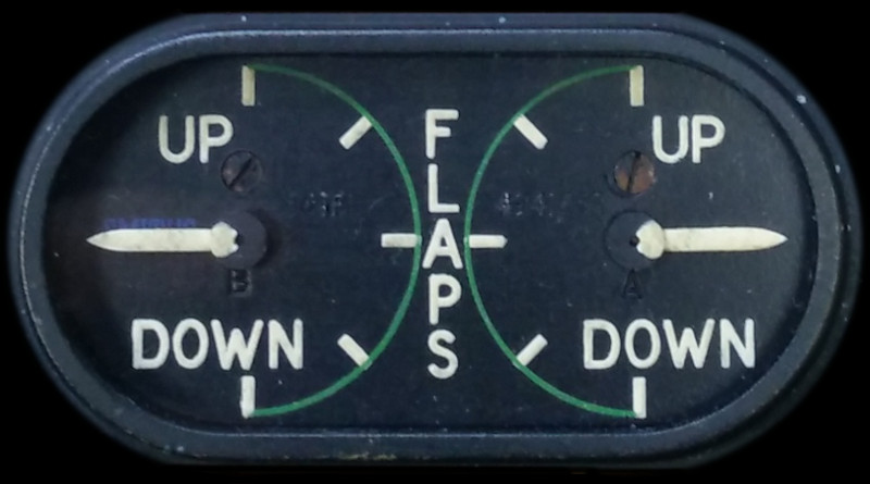
DUAL FLAP POSITION INDICATOR TYPE 561FL
LEADING PARTICULARS
| Stores Ref. No.: | 6A/4333782 (Formerly 6A/4941, and 6A/4429) |
| Manufacturer: | Smiths |
| Connection: | Screw Terminals |
| Attachment: | Bolt, 4 BA Phillips csk | 28D/1213987 | AS.3295/3B |
| Nut, Stiff, 4 BA | 28M/1086618 | AGS.2002/B/1 | |
| Washer 4 BA, Plain | 28W/9419401 | SP10/B |
DESCRIPTION
Two of these indicators are fitted to panel A1, one to the port side for pupil use, and the other to the starboard side for instructor use.
A dual display indicator, the pointers indicate the position of the port and starboard flaps, this not only indicates if they are up or down, but also if they have become unsynchronised, which could result in roll and/or yaw.
Desynn indicator system
The Desynn system is a synchronous data transmission system, used to electrically convey angular position information from a transmitter to a remote indicator. It operates on a single DC power supply, and is not affected by changes in supply voltage, such as changing from battery to generator power
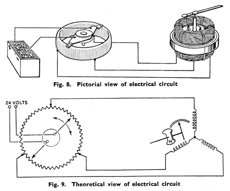
Desynn system
Extract from:
AP1275A, Vol. 1, Sect. 16, Chap. 2, AL13, Sept. 1957, Figs. 8 & 9
3 voltages are produced by a toroidal potentiometer within the transmitter housing. The toroidal potentiometer has 3 fixed tappings evenly spaced, these are connected to the remote indicator coils by aircraft wiring. Two rotating wipers are connected to the power supply such that one wiper applies 0V and the other applies +V to the potentiometer.
This wiper arrangement causes current to flow in two arcs around both sides of the toroidal potentiometer, setting up a gradient of voltage from the positive wiper to the negative wiper. The three fixed tappings are energised to a voltage proportional to the position between the wipers.
As the wipers are rotated, the voltage gradient is moved around the toroidal potentiometer, altering the voltages present at each fixed tapping. As the tapping voltages change, the currents in the indicator coils also change, causing the overall magnetic field in the indicator to rotate, and carrying the pointer with it.
This system ensures the pointer is always synchronised to the transmitter angle, it can rotate infinitely, and power supply fluctuations do not have any effect on the displayed angle.
Desynn radial arm transmitter
Edited extract from:
AP1275A, Vol. 1, Sect. 16, Chap. 2, AL13, Sept. 1957, Fig. 3
The Lightning uses flap position transmitters Type C (stbd flap) and Type D (port flap); these are internally geared (see image above) to mechanically amplify small movements, the amplification is used as the Lightning flaps only travel by 50° making a much more distinguishable display.
These transmitters have a 3:1 gearing ratio, meaning the 50° of transmitter input shaft rotation results in 150° of rotation of the indicator pointer.
SIMULATION
To simulate the signals produced by a Desynn transmitter, a driver circuit is needed to drive currents into the indicator coils.
Initially establishing electrical properties of these indicators, two scenarios are considered:
Initial tests show that the Desynn indicator coils obey ohms law for the application of DC. It was noted during testing that an increase in resistance occurs, and consequent decrease in current due to temperature rise from self-heating during operation. Nominal resistance of two coils in series is 650 Ω.
Examining one arc of the toroidal potentiometer, if the top fixed tapping is aligned with the +V wiper, with the 0V wiper bottom, the other fixed tapping connected to that arc will be at 1/3 of the full supply voltage as the arc is acting as a potential divider with 1/3 of the resistance below the tapping. For a 28 V supply, the aligned tapping will be at 28 V, and the other at 9.3V (1/3 of +V), meaning an indicator coil pair is at most presented with 18.7 V between any two terminals.
Caution: 28 V connected for a long period of time may result in over-heating and damage.
Based on simulating a 28 V power supply, as per above example with transmitter +V wiper aligned with one fixed tapping, and 18.7 V across two coils; the following design criteria are to be worked toward:
| Coil Resistance | Current Per Side | Supply Current |
|---|---|---|
| 650 Ω | 29 mA | 58 mA |
In this example of simulated 28 V operation, one drive circuit will need to source 58 mA, and the other two circuits sink 29 mA each.
REFERENCES
Indicator general and technical information:
AP1275A, Vol. 1, Sect. 16, Chap. 2, AL13, Sept. 1957, Position Indicators (Desynn Type)
AP112G-0208-16, AL29, April 1997, Desynn System
Standard Technical Training Notes (STTN):
AP3280B, Sect. 3, Chap. 5, AL25, July 1963, Desynn Instruments
T Mk.5 mechanical "Vol 1":
AP101B-1005-1A, Sect 3, Chap 4F, AL86, Aug. 1976, Flying Controls - Flaps and Air Brakes
T Mk.5 electrical "Vol 1":
AP101b-1005-1B, Sect 6, Chap 3, AL2, Jan 1965, Flying Controls - Paragraph 8
T Mk. 5 wiring diagrams:
AP101B-1005-10, Sheet 17, AL3, November 1981, Flying Controls - Flaps - Fig 5