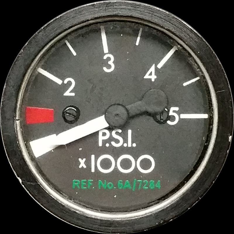
SERVICES HYDRAULIC PRESSURE INDICATOR TYPE AI756
LEADING PARTICULARS
| Stores Ref. No.: | 6A/7284 |
| Manufacturer: | Appleby & Ireland |
| Connection: | 104 Pattern / Plessey Mk. 4, small body 6-way |
DESCRIPTION
Services hydraulic system pressure indicator, electrical signals are supplied from a pressure transmitter.
The transmitter is located in the weapons pack bay, it contains a synchro control transmitter. The cockpit indicator pointer is operatied by an internal synchro receiver.
It will only operate when AC power is available, fed from 26Vac 400Hz supply busbar XK1.
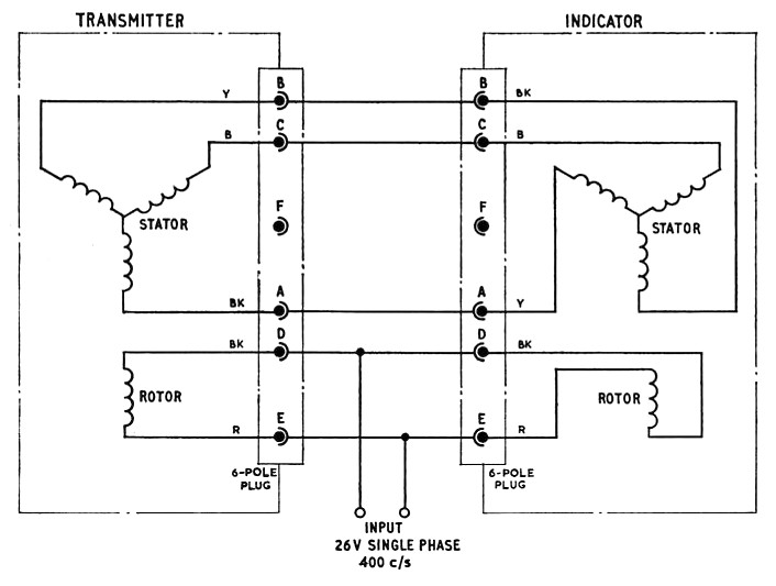
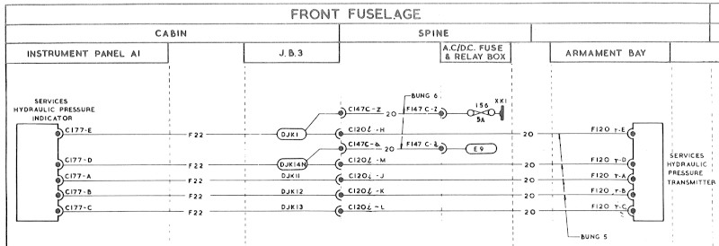
CIRCUIT DIAGRAMS
The internals of the transmitter and receiver, and typical interconnecting wiring taken from A.P.112G-0552-1, Nov 67.
T5 Lightning circuit diagram - edited drawing taken from A.P.101B-1005-1B, Sect.7, Chap.6, Fig.3, A.L.62, Feb. 74.
SIMULATION
In order to simulate this indicator I need to develop a method of replicating synchro transmitter signals.
Experiment No. 1
To just simply see this indicator operate, I connected it up to a synchro control transmitter that I had previously rescued from a skip. The transmitter was to simulate the signals of the pressure transmitter.
Luckily I have a 26Vac 400Hz rotary inverter that I also rescued from a skip a few years ago.
I cleaned up a 6 way Plessey Mk4 socket and made up a test cable to link the indicator to the synchro and inverter.
The video below shows the indicator pointer following the angle of the transmitter shaft very accurately:
REFERENCES
Indicator general and technical information:
A.P.112G-0552-1, Nov 67 - Appleby & Ireland pressure indicator
T Mk.5 electrical "Vol. 1":
A.P.101B-1005-1B, Sect.7, Chap.6, A.L.62, Feb. 74 - miscellaneous instruments - Paragraph 7