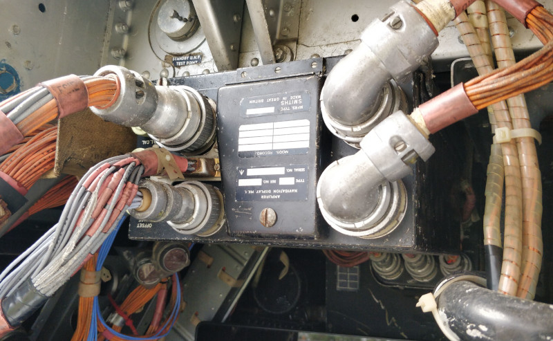
NAVIGATION DISPLAY AMPLIFIER TYPE C
LEADING PARTICULARS
| Stores Ref. No.: | 6TD/732, later 6TD/1048470 |
| Manufacturer: | Smiths |
| Attachment: | Mounting tray |
| Connection: | connector-104-pattern-plessey-mk4.htm, and a D type. |
DESCRIPTION
The navigation display amplifier provides closed loop control for the servomotors of the navigation display indicator, positioning the compass ring, TACAN/ILS roller blind and ILS glidepath bar. A monitoring amplifier also checks for synchronisation between the master reference gyro (MRG) and the fin-mounted compass detector.
It also includes test and calibration adjustment facilities.
After looking for years and asking many people, out of the blue my mate Trev called as he stumbled across one still installed in his F Mk. 6 Lightning cockpit XR757, we agreed a swap, and here it is:
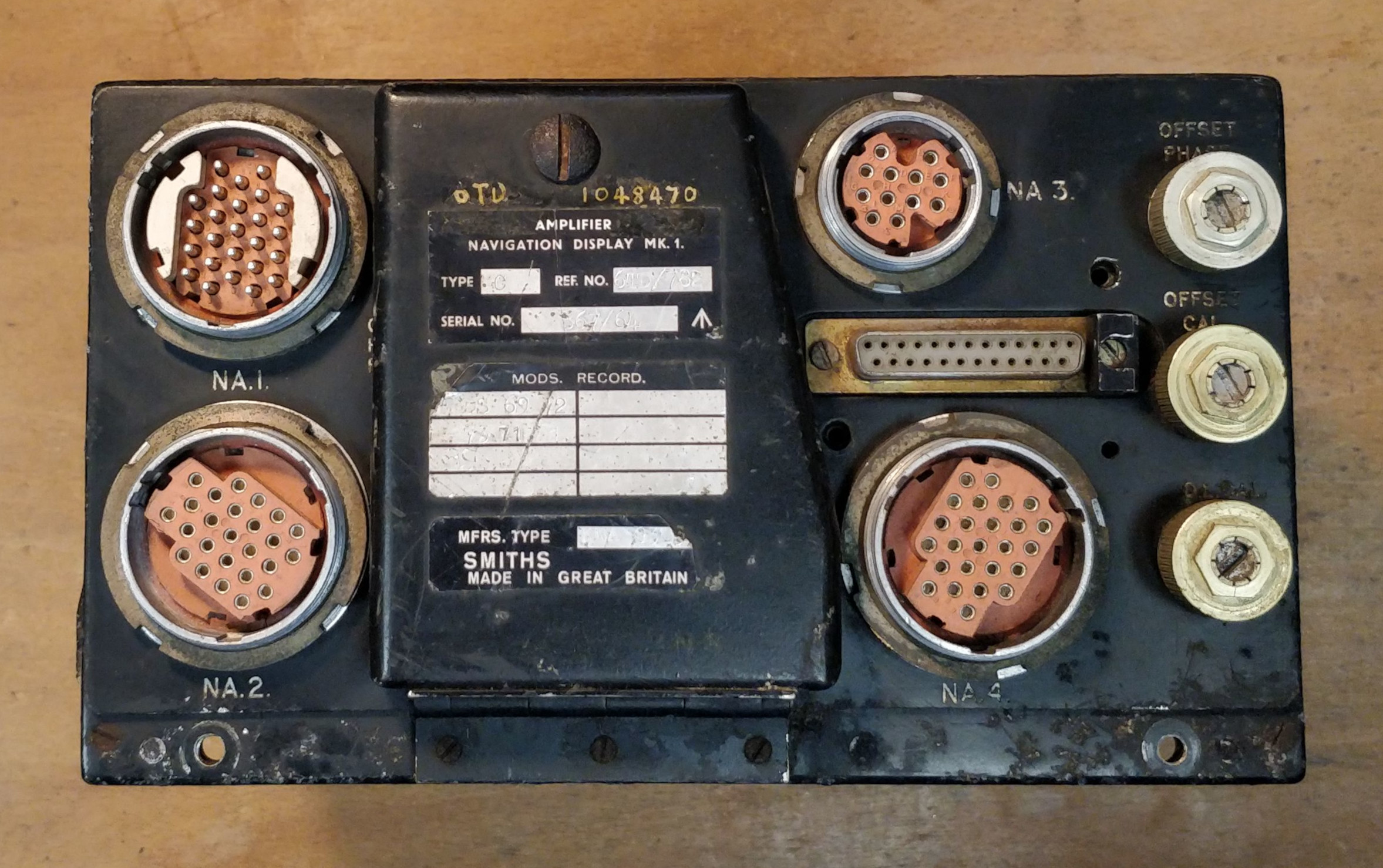
Navigation display amplifier
Some of the calibration potentiometers and switches are hidden behind a central hinged cover. Why the ones to the side are not is probably a question that will never be answered.
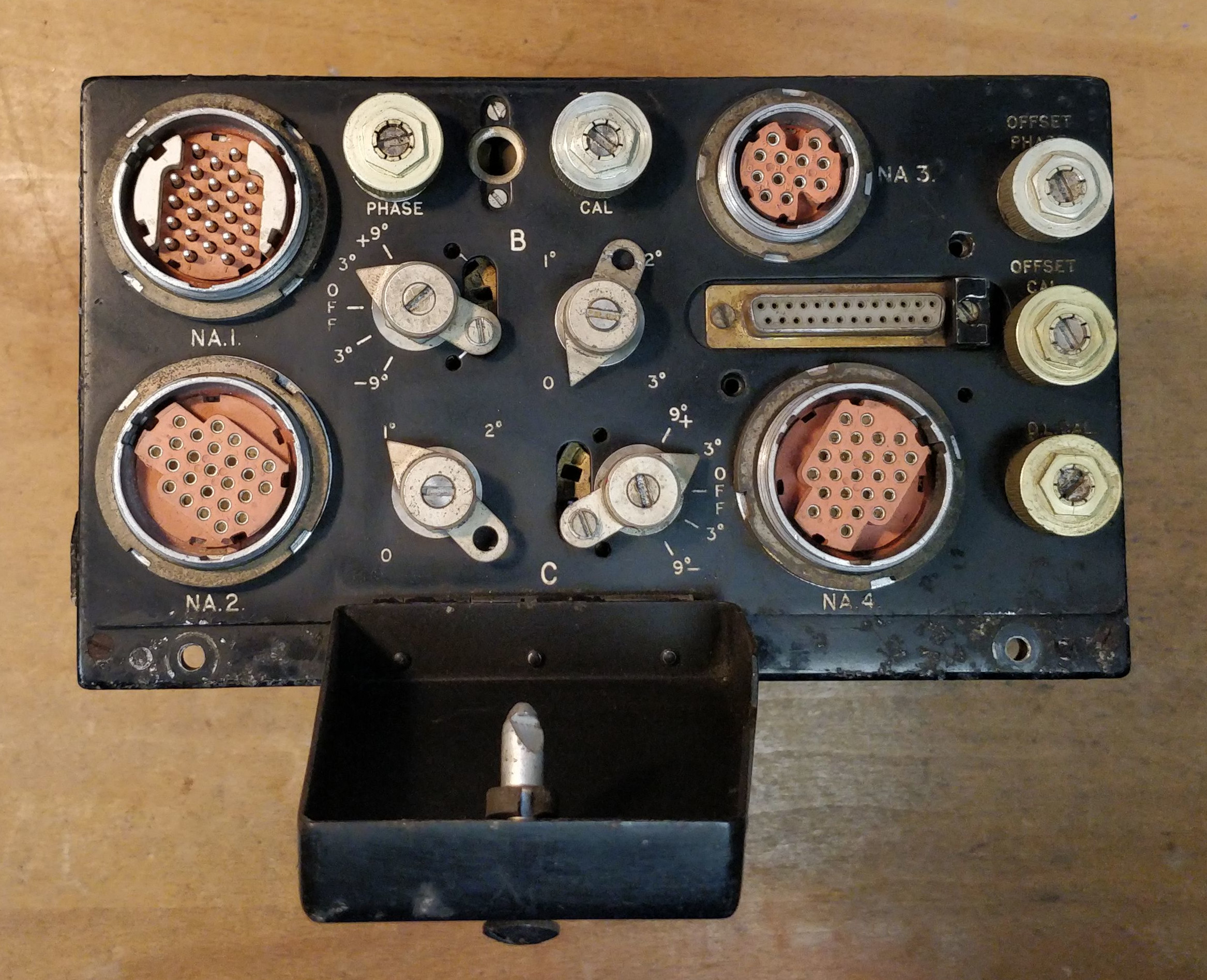
Navigation display amplifier
Left: servo-amplifiers. Middle: power supply unit and monitoring amplifier. Right: Connectors and calibration pots and switches.
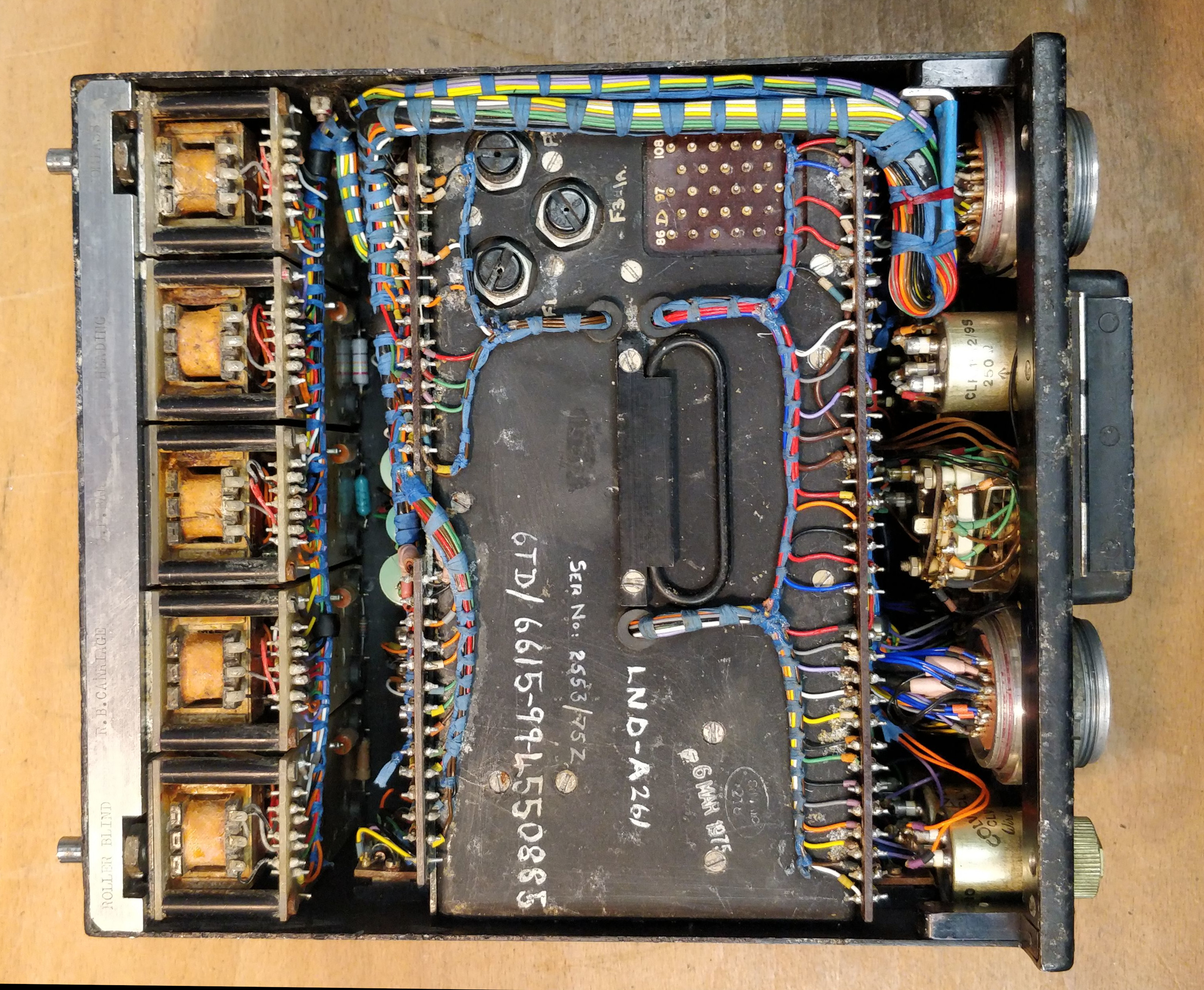
Navigation display amplifier, cover removed
The servo-amplifier modules are mounted to a rather extravagant and heavy lump of stainless steel, etched with the name of each amplifier.
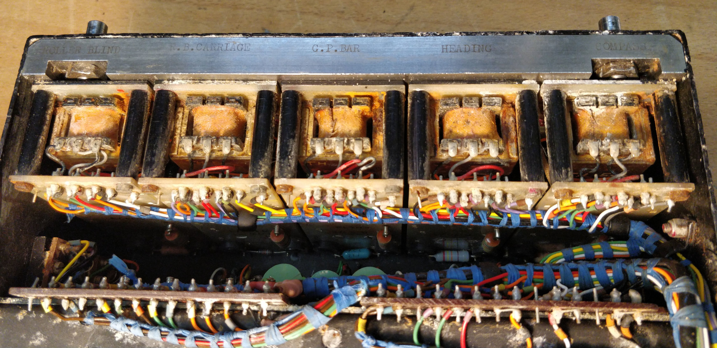
Servo amplifier modules
The motor drive transistors are all mounted to little pieces of Bakelite board, and fitted in really awkward spaces around the chassis.
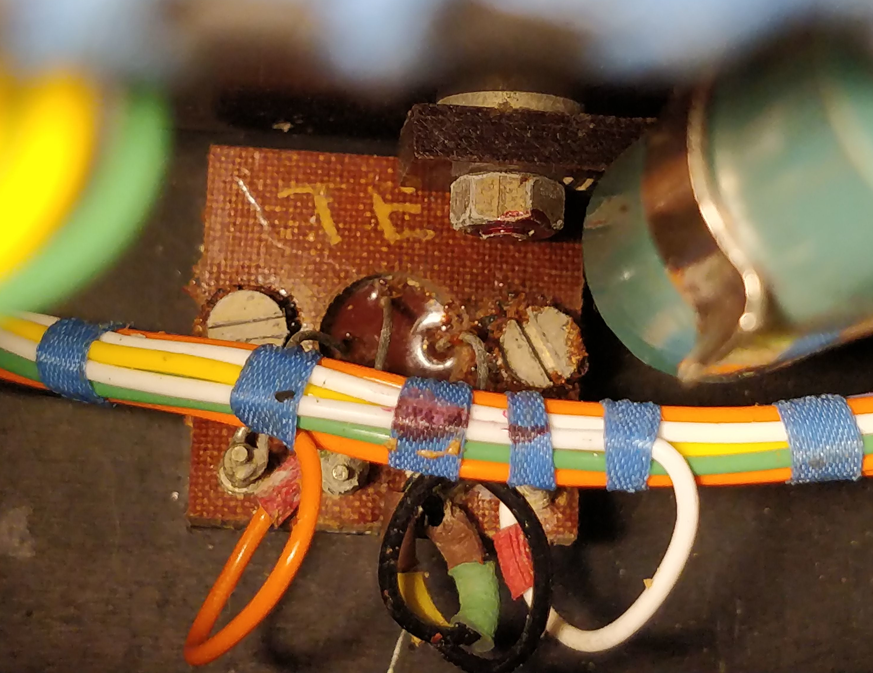
Motor drive transistor
SIMULATION
I restored and configured a set of connector-104-pattern-plessey-mk4.htm, plus a 25 way D type.
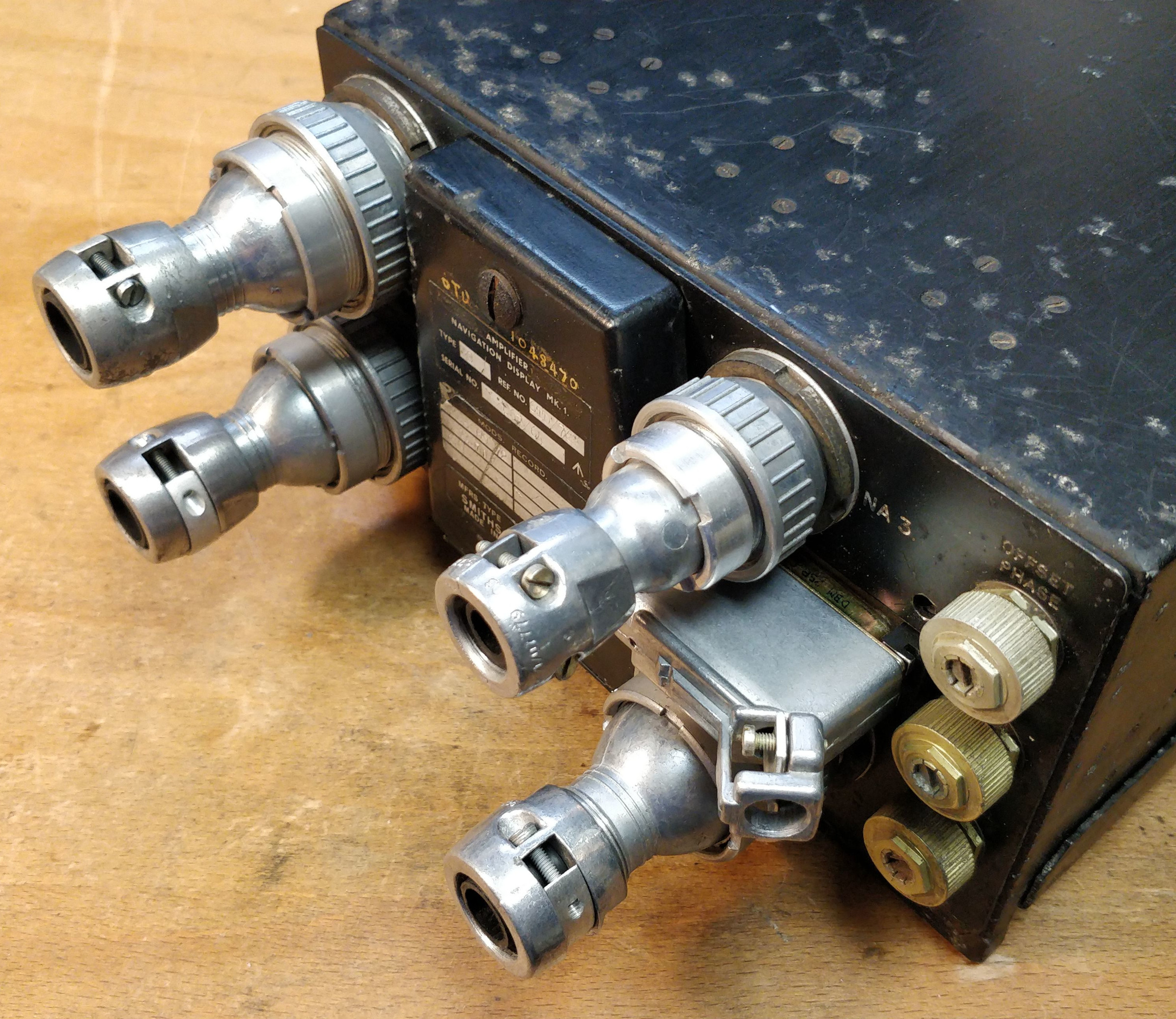
Navigation display amplifier connectors
The inputs to the amplifier are mostly synchro or resolver, with a slightly different signal from the compass detector. Interface to the TACAN offset computer may need some work to output the offset and range data to the flight simulator.
REFERENCES
"IFIS" overview:
A.P.3456D, Part 2, Chap 3, A.L.14, May 1969 - Integrated Flight Instrument System - Paragraph 8
F Mk. 3, T Mk. 5 and F Mk. 6 aircrew manual:
A.P.101B-1003, 5 & 6A, Part 1, Chapter 7, A.L.2, Nov 1984 - Instruments - Paragraph 18
T Mk.5 electrical "Vol. 1":
A.P.101B, Sect.7, Chap.3C, A.L.67, May 1975 - Dynamic Flight Reference System - Paragraph 11
T Mk.5 electrical "Vol. 1":
A.P.101B-1005-1B, Sect.8, Chap.1, A.L.66, Sept. 1975 - U.H.F./V.H.F., Intercommunication and Telebriefing - Data Link paragraph 26, Violet Picture paragraph 29
Smiths literature:
Smiths Leaflet F2-2 - Flight Data System
EXTERNAL LINKS:
Wikipedia ↗ - Rainbow Codenames, Violet