TACAN OFFSET COMPUTER TYPE B
LEADING PARTICULARS
| Stores Ref. No.: | 6TD/4330882 |
| Manufacturer: | SMITHS |
| Attachment: | Crate |
| Connection: | McMurdo Red Range 16 way |
| System: | TACAN |
DESCRIPTION
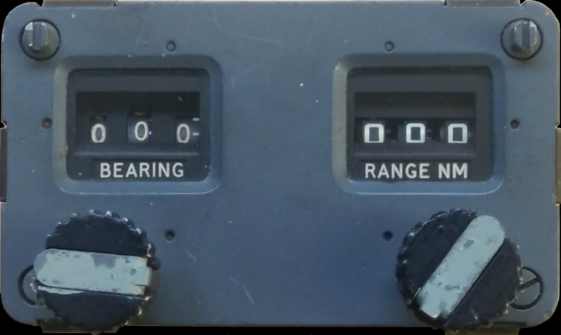
Allows for TACAN radio navigation to a homing point offset from a TACAN beacon, within a 195 NM radius.
Range is measured with a precision potentiometer, while the bearing is measured with a synchro resolver.
The synchro resolver "resolves" the bearing angle to two constituent parts, the sine and cosine of the shaft angle. Electrically these appear as two AC waveforms, whos amplitude represent the sin and cos values.
The range potentiometer is used to set the gain of two thermionic valve ("tube") amplifiers, whch amplify the sin and cos signals from the resolver. This results in an electrical representation of X and Y coordinates which can be interpreted terms of nautical miles to be added to or subtracted from the position of the TACAN beacon.
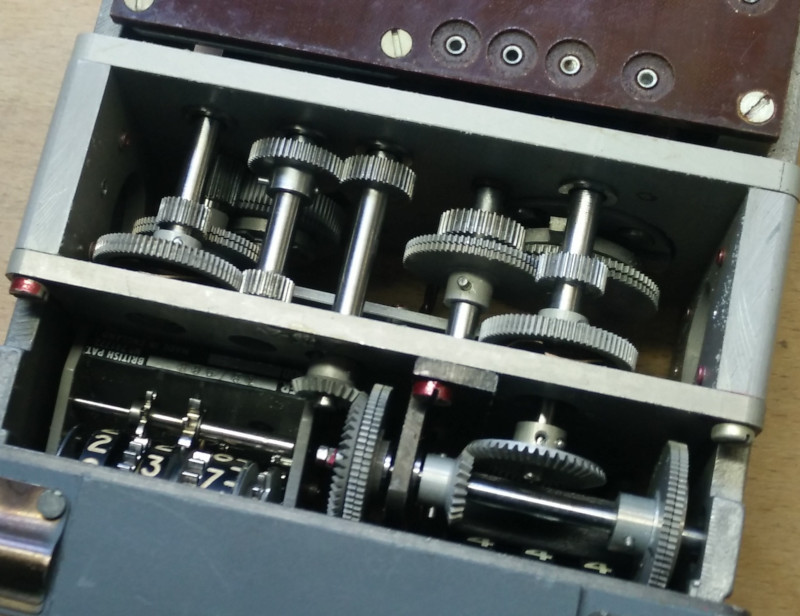
It's little examples like this that show where the tax payers' money went during the cold war era.. But hey, it produced some really beautiful engineeing as shown here, the craftsmanship of a watchmaker.
SIMULATION
Modification
This project's fundamental aim has always been to preserve the equipment without modification. However sadly in this instance, it's possible but just not practical, nor cost or time effective.

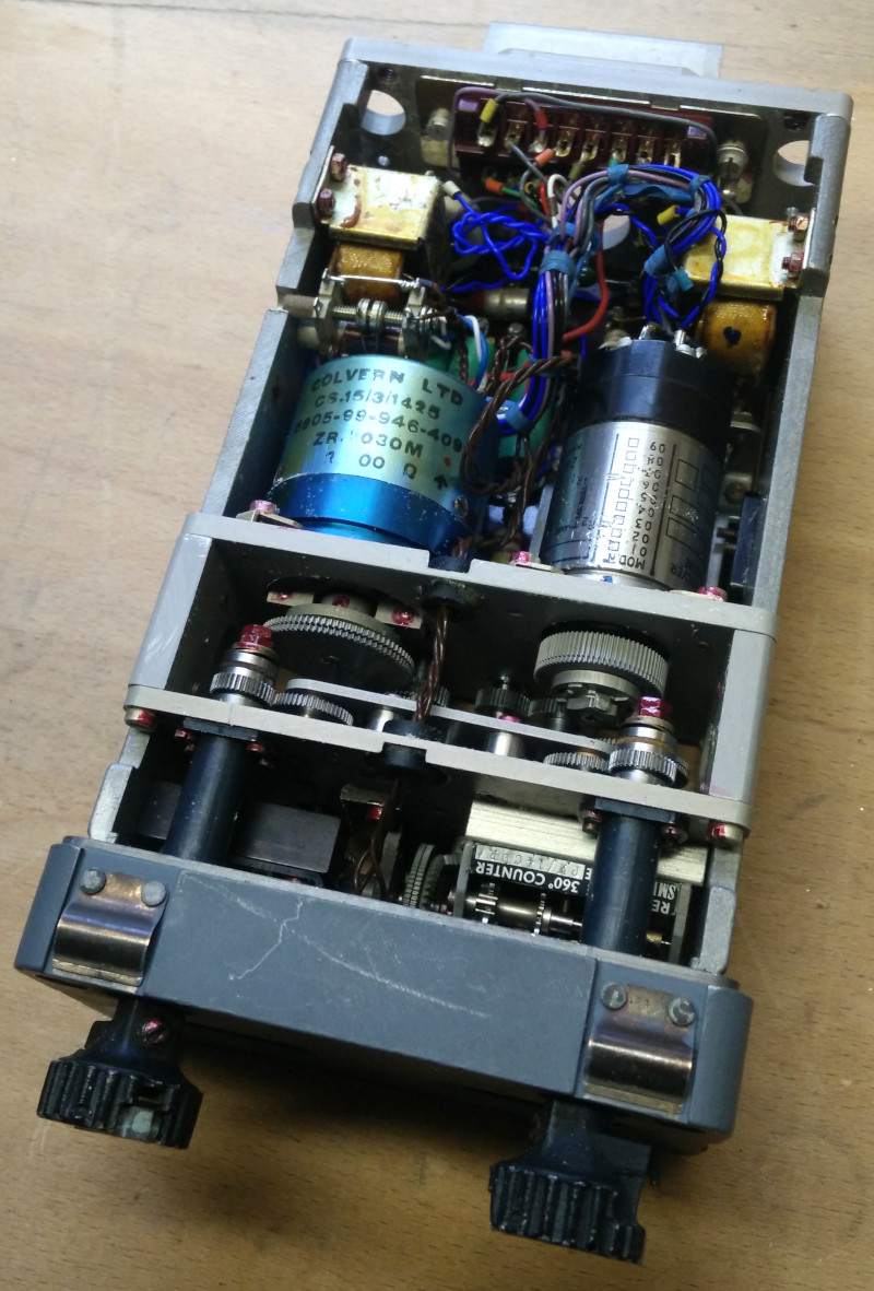
TACAN offset computer with circuit board lifted.
To utilise the potentiometer and synchro resolver, the existing circuitry sadly has been removed, allowing direct access to the potentiometer and synchro resolver. This is primarily because the existing circuit produces composite signals of both contol knobs as described above. The simulator needs to know the exact position of each knob, so going back to basics was required. Additionally the circuit utilises thermionic valves which require high voltage to operate, this would add a layer of complexity and hazard not required by this project.

TACAN offset computer, removing circuit board.
A circuit is in development to read the shaft position of the resolver and potentiometer and pass this information to the simulator.
Flightgear FGUK Lightning Model
The FGUK Lightning model did not include any calculations for the offset computer, so I went ahead and figured out how to implement it. This involved a lot of trigonometry, which was difficult for me being an area of mathematics I last touched upon at school! But with a bit of reserach and learning, I came up with a solution to the problem.
This video below is a demonstration of how the offset works. The navigation instrument is still in need of development, for example the TACAN display should show a set of concentric rings, but for now this proves the offset works (best in full-screen to see the details):
The maths works by establishing Cartesian X,Y coordinates (in NM) of the beacon from the aircraft (by sin and cos), and also establishing X,Y coordinates from the beacon to the offset point. Then by adding the offset coordinates to the beacon coordinates to find the X,Y coordinate of the offset homing point from the aircraft, I then turn those coordinates back into a bearing (by atan2) and range (by pythagoras). After playing around with a LibreOffice Calc spreadsheet to prove the maths, this was then scripted in Nasal for the Lightning model.
REFERENCES
F Mk. 3, T Mk. 5 and F Mk. 6 aircrew manual:
A.P.101B-1003, 5 & 6A, Part 1, Chapter 7, A.L.2, Nov 84 - Instruments - Paragraph 28
T Mk.5 electrical "Vol. 1":
AP101B, Vol.1B, Section 7, Chapter 3C, A.L.67, Nov 75 - Dynamic Flight Reference System - Paragraph 20
Flying manual:
A.P.129, Vol.1 Sect.2, Chap.5, 6th Edition, Feb. 1962 - TACAN
Smiths literature:
Smiths Leaflet F2-2 - Flight Data System