ATTITUDE INDICATOR TYPE F4C
LEADING PARTICULARS
| Stores Ref. No.: | 6TD/7287 |
| Manufacturer: | SMITHS |
| Attachment: | Crate |
| Connection: | Mc.Murdo red range 24 way, internally D-type 25 way |
DESCRIPTION
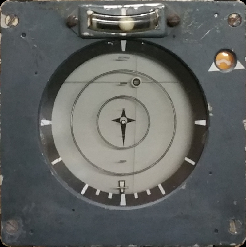
This indicator presents information regarding attitude in terms of bank and elevation angles in the form of an artificial horizon, plus flight director indicator bead/button.
The main artificial horizon is formed of a black and white roller blind, which moves around rollers for elevation angle. The rollers are mounted within an overhung carriage which rotates on a spindle for bank angle. At its extremes it displays markers for zenith (straight up) and nadir (straight down), pictured above in stereotypical Lightning zenith position for a vertical climb.

Main spindle bearing, with cover removed revealing slip ring electrical connections to the roller blind motor and synchro.
The flight director button is positioned by two wires, strung under tension across the front of the indicator. These wires are held by small carriages at their ends which slide across in pairs to position the wire and button vertically and horizontally.
There is also an orange window which is internally covered over by a solenoid actuated shutter to indicate power health. The orange window is illuminated as per the main display area.
The main display area is illuminated by 4 bulbs, via red acrylic / Perspex.
The motors are all quadrature phase type, and angle feedback is via synchro control transmitters for elevation and bank angles, and precision potentiometers for the flight director button position.
TESTING & REPAIR
Luckily I was given a scanned copy of AP102B-0303-1 which contained a great description and circuit diagram of the attitude indicator, this happened to also coincide (within weeks) with the acquisition of the correct Mc. Murdo Red connector, suddenly enabling testing after years of ownership.
This unit has not been modified, the initial testing was carried out with the unit in the state that I acquired it.
TEST 1
Upon the first application of 115 V AC power:
- Both X and Y axes of the flight director responded by moving to a null position (as these inputs were not energised for the test) indicating that these may work when tested with input voltages.
- The roller blind responded in elevation, and can be controlled easily by external synchro shaft angle.
- There was no response to change in bank angle synchro shaft, requiring some fault-finding.
This video of the initial testing demonstrates the control of the elevation axis of the roller blind:
In the elevation angle axis control of the roller blind was fantastic, very responsive to my inputs, and no overshoot to fast changes.
REPAIR
I started fault finding by following the circuit diagram, checking basics first; impedance of inputs, and health of fuses. Upon withdrawing the power supply and amplifier unit, and examining the bank angle motor and synchro, I found a wire was broken off a bank motor terminal. This was terminal 3, one end of the REF field winding.
I removed the terminal lug to de-solder the remains of the old wire connection. Preparing the wire end requires special wire strippers, being PTFE insulated, vintage lead based solder was used to repair the joint.

Violet wire identified as "5" (green marker) with re-soldered joint to terminal 3 of the bank servo motor.
TEST 2
After completing the repair, and re-assembling the indicator, the next test showed a successful repair!
OTHER REPAIRS
FLIGHT DIRECTOR BUTTON WIRES
Someone has messed around with it in the past, as the wires holding the flight director button are a bit broken, needing replacement, but nothing has been modified or changed. Ref: preservation. As I don't have a copy of AP112B-0303-3 I don't know what type of wire material is used to mount the flight director button (topic -3 is the illustrated parts catalogue). If anyone reading this does know, or has a copy of the topic 3, please do get in touch.
SIMULATION
Bank and elevation data is already available in the Flightgear model, so only some simulator programming work in going to be needed for the flight director button position.
For the artificial horizon, the plan is to develop an "electronic synchro control transmitter" circuit to simulate the signals that are produced by the MRG (Master Reference Gyro) synchros. These electrical signals have a variable voltage up to 90 V AC at 400 Hz.
The inputs for the flight director system is just two variable DC voltages, so will be easy to simulate.
The turn and slip indicator is purely a ball in a glass tube, and therefore there is unfortunately no easy way of directly simulating its behaviour
REFERENCES
"IFIS" overview:
A.P.3456D, Part 2, Chap 3, A.L.14, May 1969 - Integrated Flight Instrument System - Paragraph 7
F Mk. 3, T Mk. 5 and F Mk. 6 aircrew manual:
A.P.101B-1003, 5 & 6A, Part 1, Chapter 7, A.L.2, Nov 1984 - Instruments - Paragraph 14
T Mk.5 electrical "Vol. 1":
A.P.101B, Sect.7, Chap.3C, A.L.67, May 1975 - Dynamic Flight Reference System - Paragraph 24
Smiths literature:
Smiths Leaflet F2-2 - Flight Data System