TACAN CONTROL UNIT TYPE 9273A
LEADING PARTICULARS
| Stores Ref. No.: | 10L/16867 |
| Manufacturer: | Standard Telephones and Cables (STC) |
| Attachment: | Dzus D5 Panel Line quarter turn fasteners |
| Connection: | UK-AN / MIL-C-5015 20-27, 14 way |
| Installation: | A.R.I. 18107 |
| Systems: | TACAN & VHF/UHF, Intercom and Telebriefing |
DESCRIPTION
This control uint gives access to settings of the main TACAN T/R unit. It can set the T/R unit to one of 126 channels, and Air/Air or Air/Ground modes, and can adjust the volume of the Morse code signal.
According to the Lightning T Mk.5 Vol.1 manual, the aircraft was fitted with either:
| Transmitter/Receiver Type: | Control Unit Type: | Modes: |
|---|---|---|
| RT.220C-ARN-21C (10D/22927) | | 9273 (10L/16324) | | REC - BRG/DIST |
| RT.636-ARN-72 (10D/26801)
[AKA: ARN-21D] |
| 9273/A (10L/16867) | | A/G - A/A |
The notable difference between the control unit types is simply the markings of the mode switch (as above).
I am yet to see a photograph of a T Mk.5 or T Mk.55 with the earlier controller type 9273 (however, the T Mk.4 pilot's notes do show it) so am building this simulator with the later 9273/A controller (for the ARN-72 TACAN T/R unit).

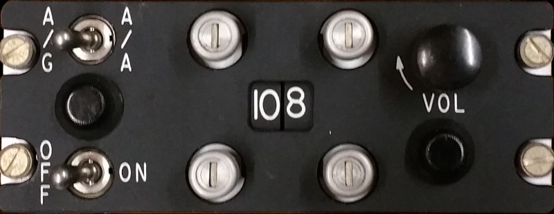
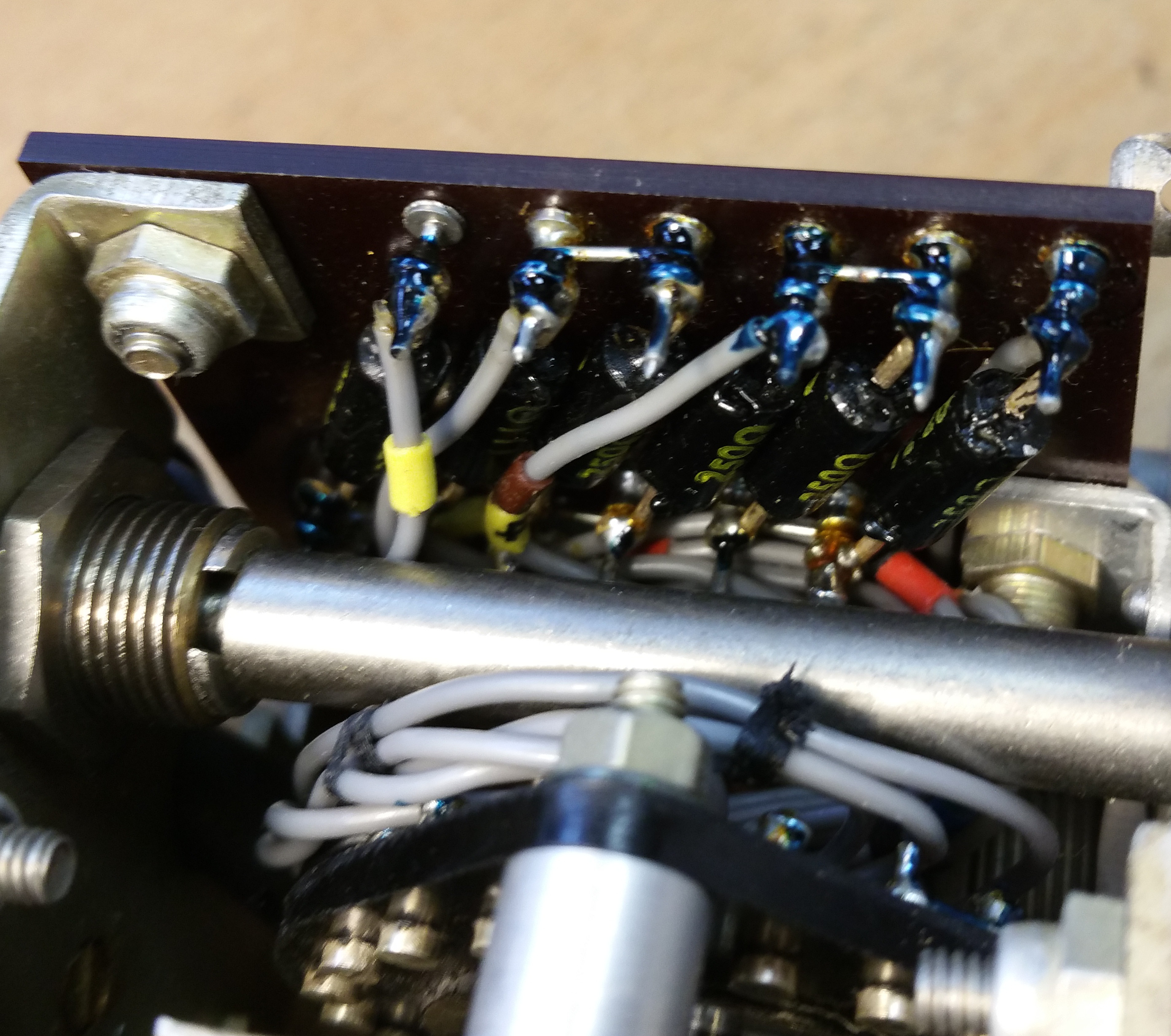
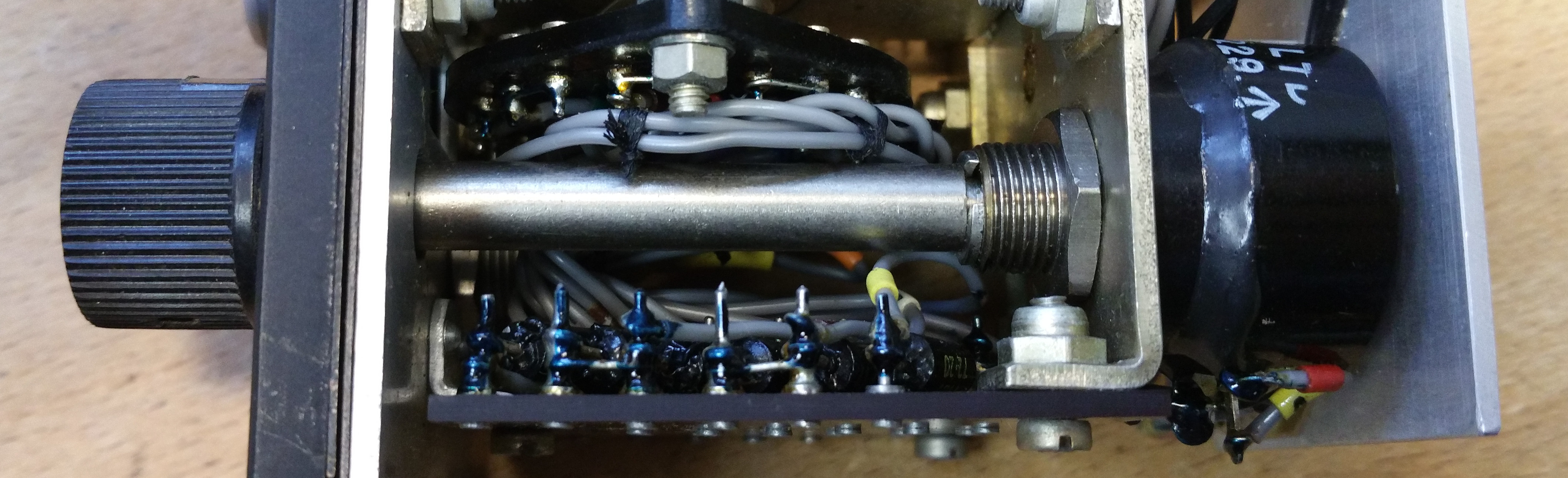
TACAN contro unit Type 9273A, cover removed
The control unit has a switch for power marked ON - OFF, switch for air-to-air / air-to-ground mode marked A/A - A/G, 4 push buttons for selecting TACAN channels, which are displayed by illuminated rotary indicators, and a knob to control the TACAN audio volume marked VOL.
TACAN is modelled within Flightgear so this control unit will be integrated to provide correct functionality.
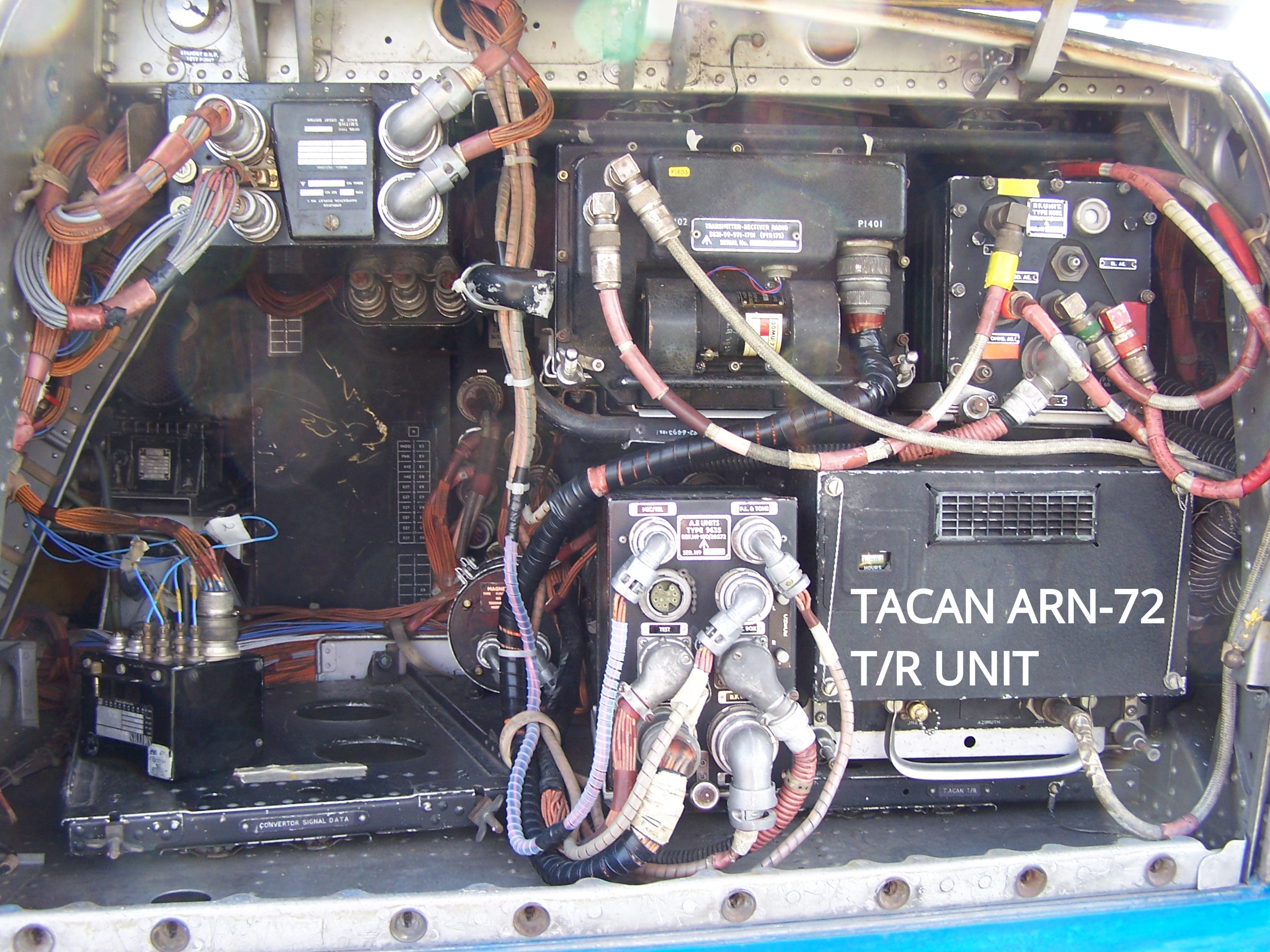
ARN-72 TACAN transmitter/receiver unit shown the
port "elephant's ear" of T Mk.5, XS458 22-04-2006
When the ARN-72 TACAN system was designed in the early 60's, only 126 channnels were in use globally. At some point around 1967 the number of TACAN channels in use was doubled (ref: IMSM/18/67), and the original 126 became labelled "X" channels with the new channels being labelled "Y" channels, this is why it's common to see later TACAN units with an X-Y selection. As Fightgear supports both X and Y TACAN channels, I will need to add a hidden cheat switch somewhere to make the Y channels available to make TACAN more useable in the simulated modern environment.
ADVERT
This interesting advert for the first ARN21 type (with no letter suffix), branded by STC as STARN21. It shows intention for the P1 Lightning.

STC advert - STARN21 TACAN, and P1 Lightning
Published: Aeroplane, 06-09-1957
Source: Aviation Ancestry ↗
The pilot's notes for prototype P1 WG763, reveral that no TACAN was installed, making this advert perhaps a view of the forthcoming orders of RAF aircraft. AP4700A-F-PN, the F MK.1 and 1A Pilot's notes from 1962 does include a section on TACAN installation and notes on modifications to the TACAN system installed.
RESTORATION
This control unit is unused, new-old-stock, however, it had a couple of faults.
Poor Contacts
The contact surfaces of the rotary switches for channel selection had suffered a little discolouration, which meant in places it was hard to get a reliable resistance reading. Servisol Super 10 contact cleaner rubbed on the contact faces with a tissue on the end of a screwdriver resolved this issue.
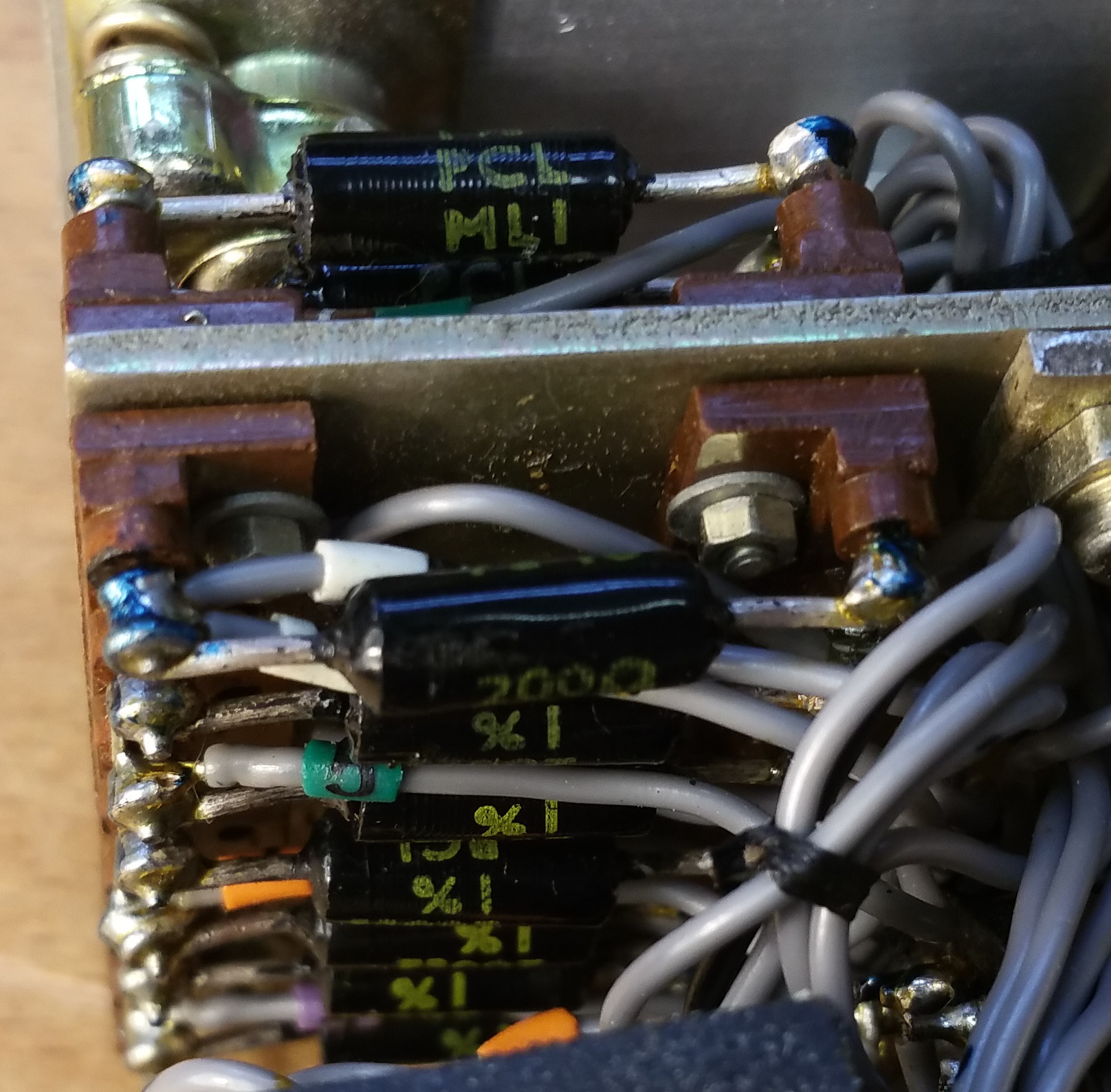
Faulty Resistors
Two wire wound resistors in the tens channel selection resistor network were found to be open-circuit.
The first of these resistors was between the switch contacts for tens channels 7-8, and the second between contacts for tens channels 8-9. As preservation is at the heart of this project, I left the original open circuit resistors in place, but added equivalent modern resistors across them. The original resistors are 200Ω, but as this is not a NPV (Nearest Preferred Value) of the regular E12 series of resistor values I had to make this value using two 100Ω resistors in series.
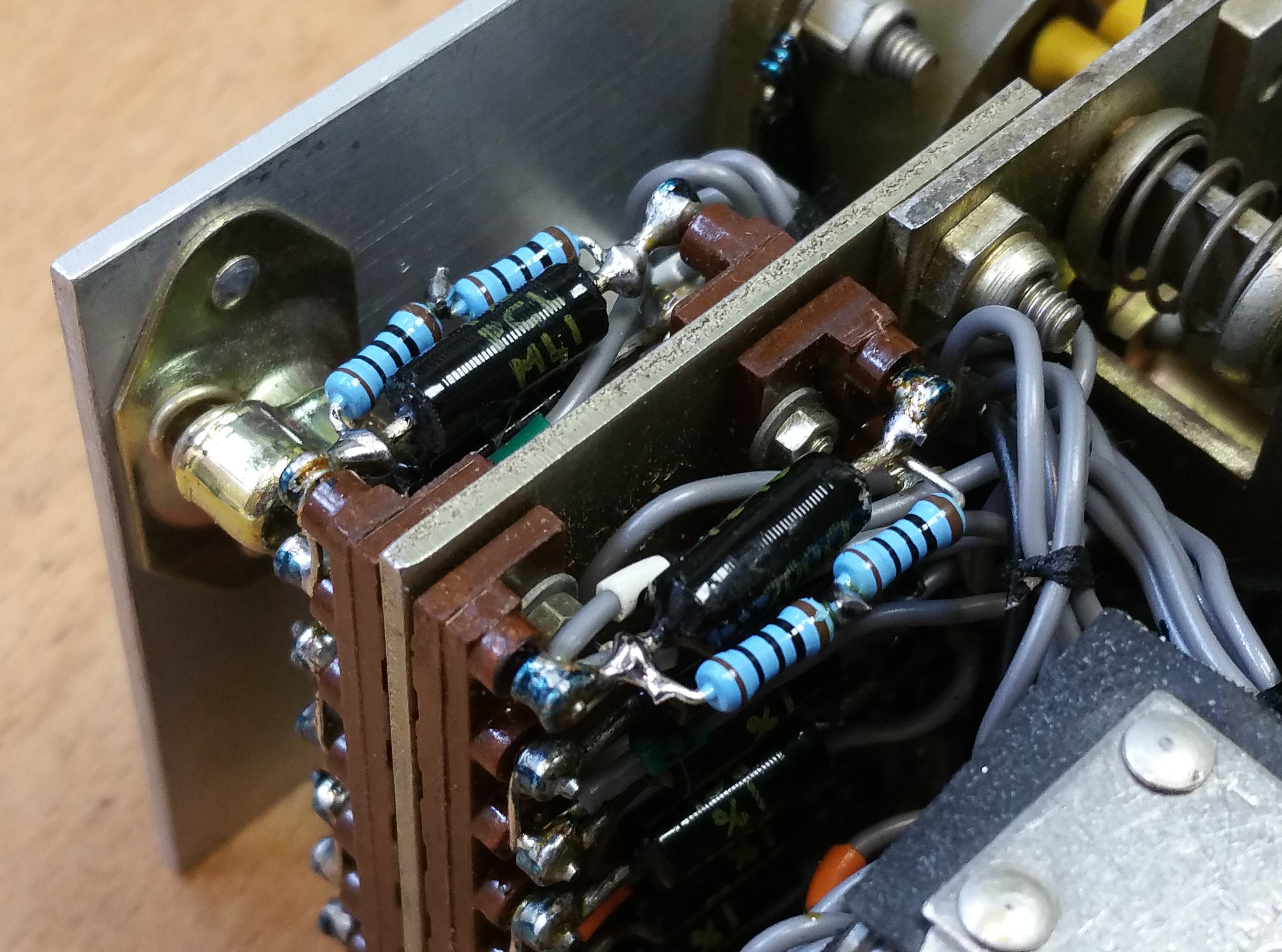
Modern carbon film resistors added.
SIMULATION
I couldn't find any documentation on the ARN-72 TACAN system, so went ahead and reverse engineered the interface to this control unit.
General
Ground connection is connector way J, and +ve supply is way H.
Illumination
The Thorn Plasteck panel is lit by two P bulbs, power is applied to way M of the connector, the ground being way J. The channel number wheels are made of perspex / clear acrylic and pass light from their sides to the letters engraved around the circumference.

TACAN contro unit Type 9273A, panel illuminated
ON - OFF Switch
The on-off switch is a double pole double throw with both poles wired, so there are two options to connect to.
When ON:
Way A is connected to way J (GND).
Way C is connected to way H.
When OFF:
Way A is open circuit.
Way C is open circuit.
A/A - A/G Switch
The A/A - A/G switch is also a double pole, but only one is used.
When A/G:
Way K is connected to way J (GND).
When A/A:
Way K is connected to way H.
Tens Channel Selection
A wire wound resistor network and rotary switches set a stepped voltage output on way F relating to number selected. the Network is grounded via way J, and powered by way B.
Units Channel Selection
A wire wound resistor network and rotary switches set a stepped voltage output on way E relating to number selected. the Network is grounded via way J, and powered by way B.
VOL Setting
The wiper of the VOL potentiometer is connected to way N, one end of the potentiometer track is connected to way J (GND), the other end of the potentiometer track is connected to way B.
In the ARN-72 system, connector way B is likely connected to the audio output of the receiver, however, I will apply a DC Voltage to it, giving me a variable DC Voltage out of way N to feed the VOL knob angle back to Flightgear.
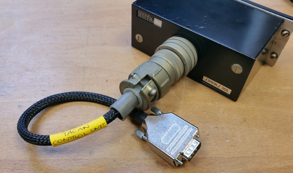
Interface
Koos Bouwknegt of vintageavionics.nl kindly donated the correct connector. The first step in building the interface was to make up a cable to a 9 way D-Type connector.
An Arduino Nano Every board was used for experimenting with serial (over USB) interface to the computer.
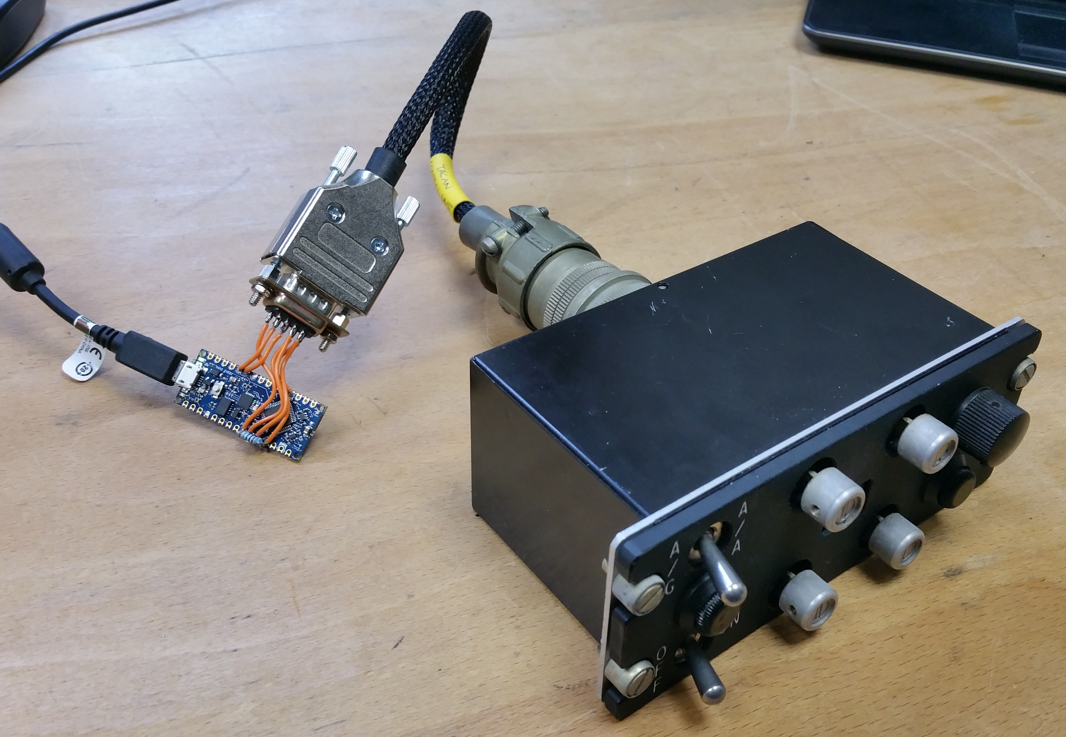
As the channel selection switches acted like stepped potentiometers, switcing different resistor values to ground, I added an external pullup resistor up to +5V and read off the values at each channel setting. I then worked out the mid-points between these values, and used these as upper and lower limits to decode the resistance values to channel numbers (see ELSE IF statements in code below). This allowed for a certain amount of tolerance due to temperature and voltage fluctuations.
Experiment No. 1
Really pleasing results of the intial experiment, all control functions are correctly reporting to the Arduino serial monitor.
Experiment No. 2
After configuring a protocol .xml file I was able to read the serial data values into Flightgear and have the TACAN control unit update the TACAN channel numbers in the Flightgear radio dualogue box.
For the sake of this experiment I only sent the TACAN channel numbers, so the below code has lines commented out regarding other controls:
/*
 * Scott Bouchard. www.scottbouch.com
 * 02-05-2022 initial.
 *
 * EE Lightning TACAN control unit type 9273A Stores Ref.: 10L/16867
 *
 * Arduino Nano Every
 * External 1K pullup resistors between 5V and A5 and A7 for tens and units selection.
 * 5V applied to top of Vol potentiometer.
 * Arduino internal pullups used on A/A-A/G and ON-OFF switches, grounded in control unit.
 */

// Set output pin numbers (not used for this experiment)
//int plPin = 6;    // Panel lighting PWM (D6)

// Set input pin numbers
int onoffPin = 7; // (D7, 25)
int agaaPin = 8;  // (D8)
int volPin = A6;   // (A6)
int unitsPin = A5;  // (A5)
int tensPin = A7;  // (A7)

void setup() {

  Serial.begin(9600);

// Outputs (not used for this experiment)
//  pinMode(plPin, OUTPUT);

// Inputs
  pinMode(onoffPin, INPUT_PULLUP);
  pinMode(agaaPin, INPUT_PULLUP);
  pinMode(volPin, INPUT);
  pinMode(unitsPin, INPUT);
  pinMode(tensPin, INPUT);

}

void send() {
  bool onoff = digitalRead(onoffPin);
  bool agaa = digitalRead(agaaPin);
  int unitsRaw = analogRead(unitsPin);
  int tensRaw = analogRead(tensPin);
  int vol = analogRead(volPin);

  int units;
  int tens;

// Decode voltages from channel selectors
  if (unitsRaw >= 0 && unitsRaw < 186)
    {units = 0;}
   else if (unitsRaw >= 186 && unitsRaw < 330)
    {units = 1;}
   else if (unitsRaw >= 330 && unitsRaw < 431)
    {units = 2;}
   else if (unitsRaw >= 431 && unitsRaw < 506)
    {units = 3;}
   else if (unitsRaw >= 506 && unitsRaw < 565)
    {units = 4;}
   else if (unitsRaw >= 565 && unitsRaw < 611)
    {units = 5;}
   else if (unitsRaw >= 611 && unitsRaw < 643)
    {units = 6;}
   else if (unitsRaw >= 643 && unitsRaw < 675)
    {units = 7;}
   else if (unitsRaw >= 675 && unitsRaw < 707)
    {units = 8;}
  else
    {units = 9;}

  if (tensRaw >= 0 && tensRaw < 223)
    {tens = 0;}
   else if (tensRaw >= 223 && tensRaw < 332)
    {tens = 1;}
   else if (tensRaw >= 332 && tensRaw < 415)
    {tens = 2;}
   else if (tensRaw >= 415 && tensRaw < 480)
    {tens = 3;}
   else if (tensRaw >= 480 && tensRaw < 533)
    {tens = 4;}
   else if (tensRaw >= 533 && tensRaw < 576)
    {tens = 5;}
   else if (tensRaw >= 576 && tensRaw < 612)
    {tens = 6;}
   else if (tensRaw >= 612 && tensRaw < 643)
    {tens = 7;}
   else if (tensRaw >= 643 && tensRaw < 669)
    {tens = 8;}
   else if (tensRaw >= 669 && tensRaw < 692)
    {tens = 9;}
   else if (tensRaw >= 692 && tensRaw < 713)
    {tens = 10;}
   else if (tensRaw >= 713 && tensRaw < 731)
    {tens = 11;}
  else
    {tens = 12;}

// Send data out over serial (ignoring toggle switches and VOL pot for testing)
//  Serial.print(!onoff);
//  Serial.print(",");
//  Serial.print(agaa);
//  Serial.print(",");
  Serial.print(tens);
  Serial.print(units);
//  Serial.print(",");
//  Serial.print(vol);
  Serial.print("\n");
  }

void loop() {
  send();
}
The following tacan.xml protocol file was used for testing.
Located at: ..../fgdata/protocol/tacan.xml
This .xml protocol file is specified in Flightgear with the command option:
--generic=serial,in,30,/dev/ttyACM0,9600,tacan
I was really pleased to see this working: original un-modified 1960's technology, interfaced to a modern flight simulator, using a low budget board, and all open source software.
CIRCUIT DIAGRAM
Control Unit
I don't have the exact diagram for the Type 9273A control unit, however the circuits of the C-886 and C-1763 control units reveal the pinouts as being very similar, the only fundamental difference is in the labelling and operation of the mode and power switches, and one extra pin being used.
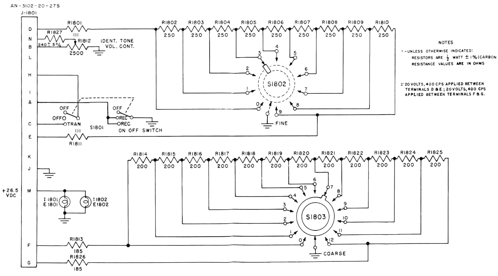
C-886 control unit circuit diagram.
Courtesy vintageavionics.nl.
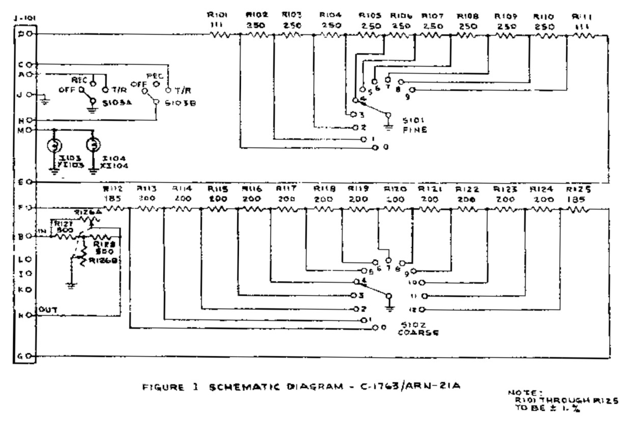
C-1763 control unit circuit diagram.
Courtesy vintageavionics.nl.
Power Supplies
The TACAN T/R unit is fed by a 28V DC supply, and a 115V AC supply, via a dedicated transformer fed from the 200V AC supply.

AP101B-1005-10, Sheet 52, Fig 3, AL3, Nov 81.
REFERENCES
F Mk. 3, T Mk. 5 and F Mk. 6 aircrew manual:
A.P.101B-1003, 5 & 6A, Part 1, Chapter 7, A.L.2, Nov 84 - Instruments - Paragraph 30
T Mk.5 electrical "Vol. 1":
AP4700E, Vol.1, Book 2, Sect.9, Chap.1, A.L.1, Nov 64 - Paragraph 9
T Mk. 5 wiring diagrams:
AP101B-1005-10, Sheet 37, A.L.3, Nov 1981, Cabin Lighting, Starboard
AP101B-1005-10, Sheet 55, A.L.3, Nov 1981, VHF, UHF, Intercommunication and Telebriefing
AP101B-1005-10, Sheet 56, A.L.3, Nov 1981, Radio and Radar Installations - Fig 3, TACAN
Flying manual:
A.P.129, Vol.1 Sect.2, Chap.5, 6th Edition, Feb. 1962 - TACAN
NATO Memorandum - TACAN (source: archives.nato.int↗)
SGM/226/64, TACAN, 22 June 1964
NATO Memorandum - TACAN Channel Doubling (source: archives.nato.int↗)
IMSM/18/67, TACAN Channel Doubling, 14 March 1967
EXTERNAL LINKS
TACAN information:
vintageavionics.nl