VHF/UHF, INTERCOMMUNICATION & TELEBRIEFING
DESCRIPTION
In order to add to the realism, this build will be using some real components as used in the Lightning T Mk.5 and T Mk.55 intercom and radio system, which can be connected to a genuine headset or flying helmet.
The main aim is to make the audio experience as close to real as possible. I have some parts of the UHF/VHF and intercom. system, which have allowed me to record audio samples to include in the FGUK Lightning model.
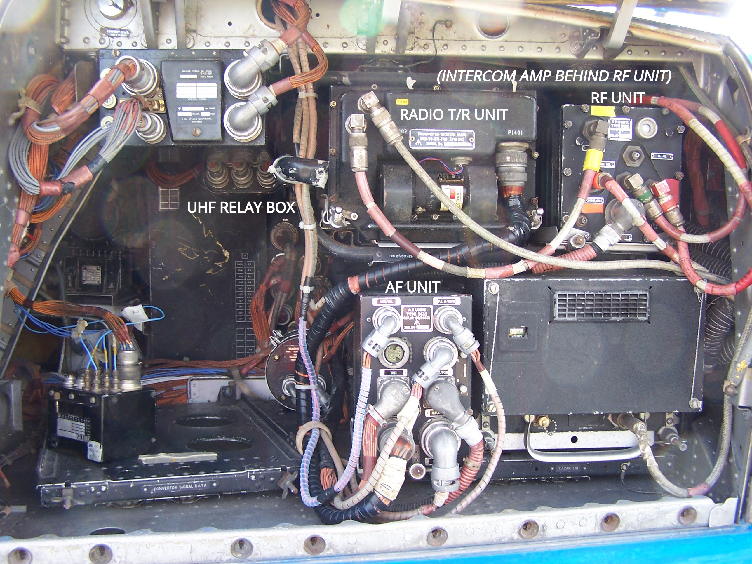
Radio communications system in the
port "elephant's ear" of T Mk.5, XS458 22-04-2006
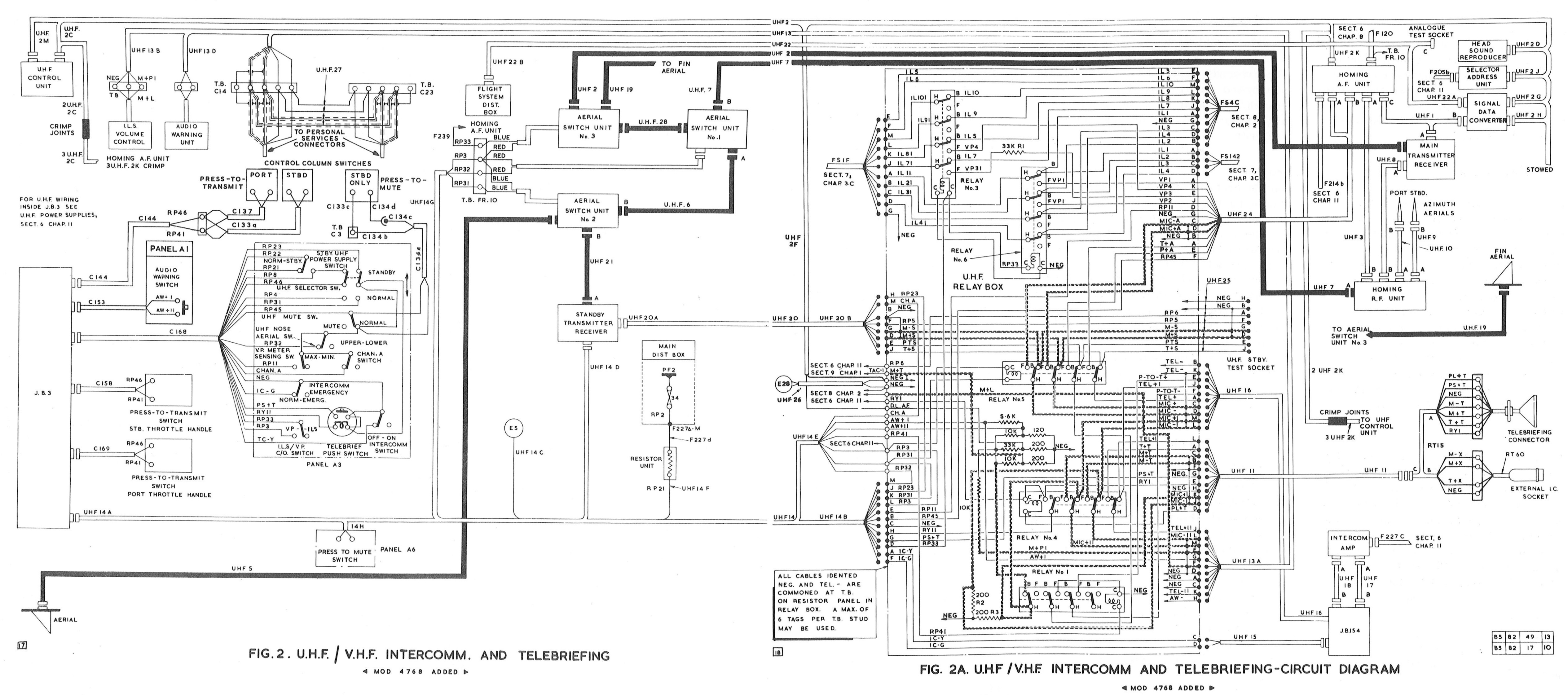
Edited extract from
AP101B-1005-1B, Sect.8, Chap.1, A.L.66, Sept.75, Fig. 2&2A
UHF VHF Intercom and Telebrief
INTERCOM.
The twin seat lightnings have an intercommunication system to allow conversation between the two crew members, and the ground crew (abbreviated to "intercom." in the aircraft labelling and documentation).
The intercom. system uses a thermionic valve amplifier type A1961, or the later transistorised A1961M , which is connected to the crew and radio using a junction box Type 154 (or simply JB154). JB154 serves to add some microphone switching logic to the system regarding the interface to the radio and other systems. This basic setup is used in various multi-seat aircraft of the era, however the Lightning also includes various other systems.
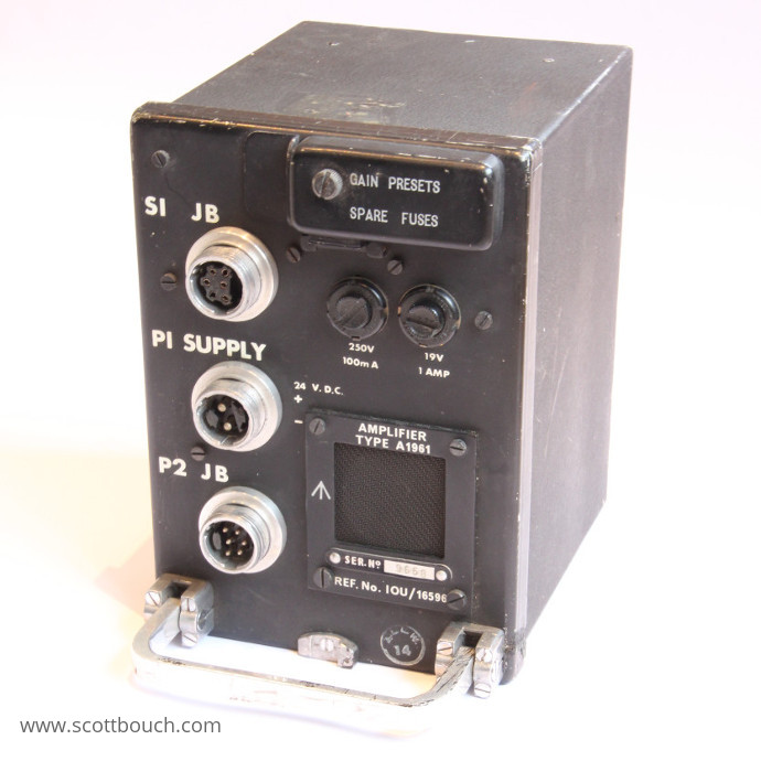
Intercom. amplifier type A1961
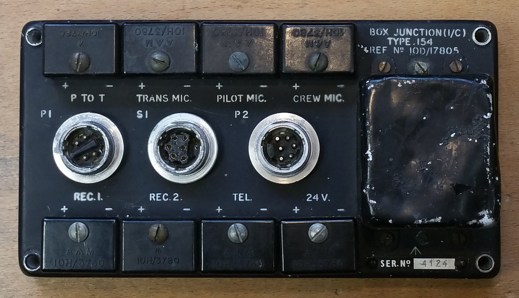
Junction box type 154
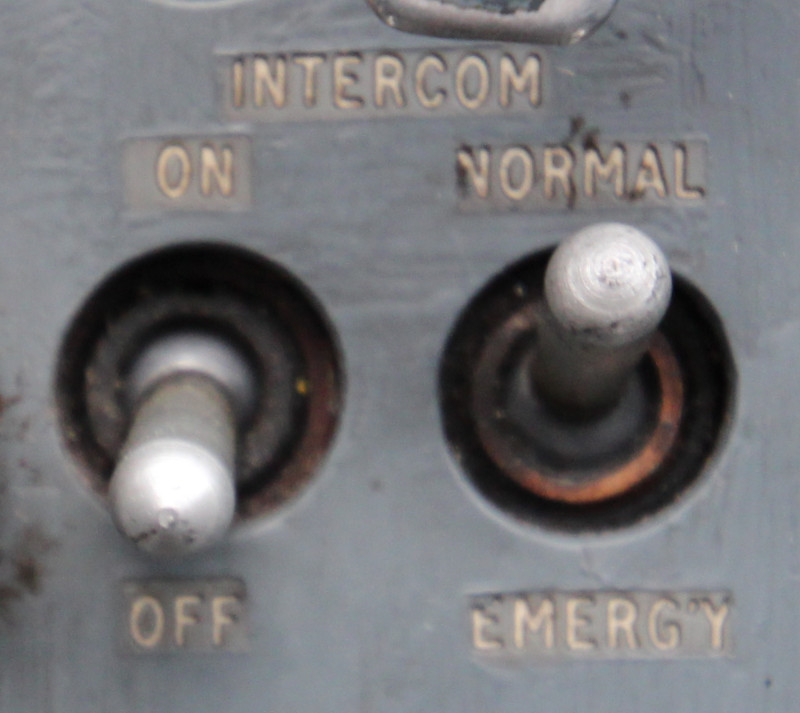
The intercom. is provided at a fixed volume, but can be selected via the "INTERCOM: ON / OFF" switch on cockpit panel A3. The "INTERCOM NORMAL / EMERGENCY" switch selects an emergency intercom mode in case of failure of the main intercom. amplifier, where under these circumstances the sidetone↗ of the main radio T/R unit is utilised as a backup intercom via the homing A.F. unit.
One issue once experienced with a Normal/Emergency relay within JB154 of T Mk. 5 Lightnig XS458 was "microphonics"", where an oxidised/tarnished relay contact in the microphone circuit was physically stimulated by engine vibration, causing a continuous intermittent circuit, resuting in this noise:
Recorded in the year 2000 at Cranfield, XS458 on a taxi-run with Brian Carroll.
Below approximately 6500 RPM (dependent on ambient temperature), R-R Avon engines are well known for significant vibrations, a combination of shaft resonance and rotating stall before the bleed valve closes.
VHF / UHF RADIO
Audio output from the main T/R unit is mixed with the intercom system audio, but its volume is independently controlled via the C1607 control unit.
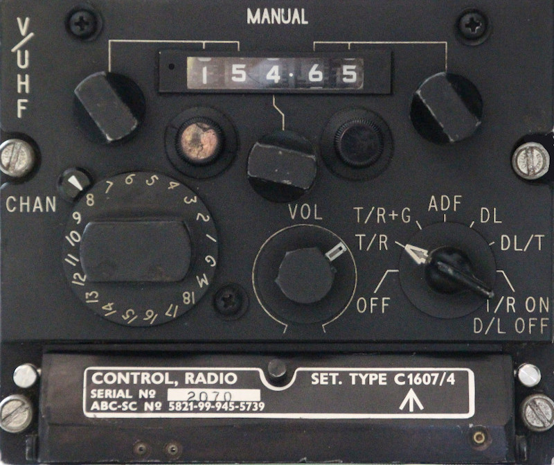
C1607 VHF / UHF control unit
The T/R unit in use is either the PTR-175 or PTR-177 depending on the requirement for Data Link. I am told by ex-RAF personnel that the equipment code "PTR" stands for Plessey Transmitter Receiver.
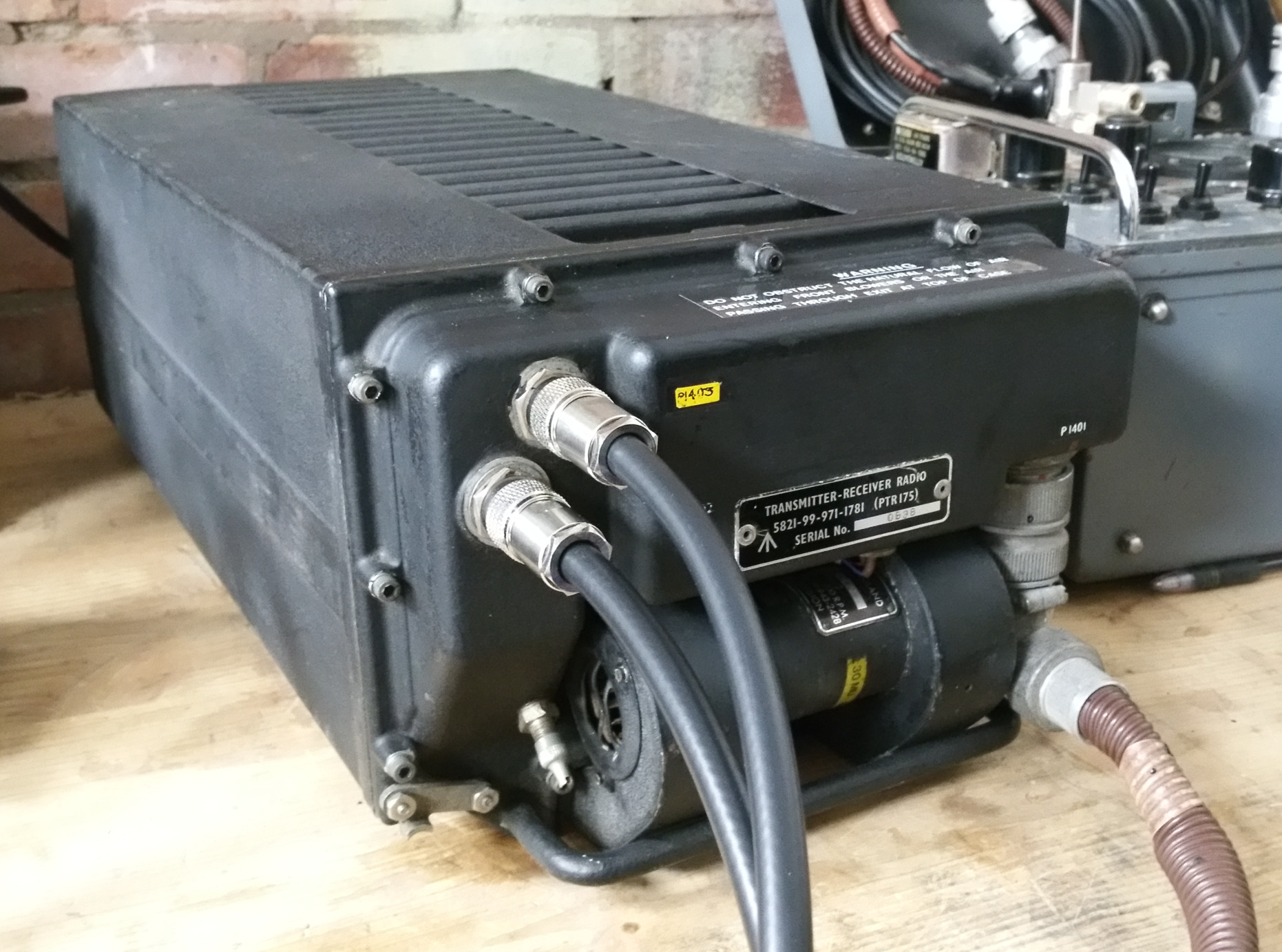
VHF / UHF PTR-175 T/R unit
A.D.F / Violet Picture
Lightnings were equipped with U.H.F. homing (or A.D.F.). Used to determine the direction of a U.H.F. radio transmitter, Useful for locating a Victor tanker, navigation aid, airfield, or search and rescue beacon. The system installed was codenamed Violet Picture, and utilised the type C navigation display's I.L.S. localiser bars to indicate UHF direction.
Visit the: Violet Picture system page.
MUTING
The VHF/UHF radio can be muted by selecting any one of three controls in the cockpit. Muting tumbler switches are located on panel A3 and panel A6, and additionally a momentary push-button on the starboard control column. Muting is activated within the radio T/R unit, leaving the intercom and other navigation aids on.
A separate audio mute switch reduces the volume of the audio warning alarm unit, as part of the warning system.
AUDIO WARNING / TACAN / ILS / HEAD SOUND REPRODUCER
Sounds from the warning system, navigation (TACAN and I.L.S. systems), and Data Link head sound reproducer (if fitted) are mixed in with the audio of the intercom and VHF/UHF systems within the UHF relay box. ILS volume is controlled by a volume knob adjacent to the ILS control unit, while the TACAN volume knob is on the TACAN control unit. Audio warning can be muted by pulling out the Audio Warning muting switch. I have configured the FGUK Lightning to produce the Morse code tones of the TACAN system, and the the ILS system, the volume of which can be set by the correct controls.
DATA LINK
Data Link was a system whereby mission information could be sent to the aircraft from a ground control point via the PTR-177 radio, giving the aircrew flight instructions via instrumentation. It was removed from Lightnings at some point, but traces of it still remain, and are important in understanding certain aspects of the Lightning cockpit. More information on: Data Link.
TELEBRIEF
As this feature is not modelled within flightgear, there is no plan to engineer it in at this point, but it can be added at a later date if needed.
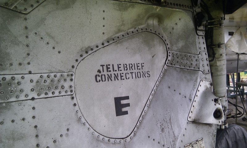
Telebrief connector under-wing location
Lightning T Mk. 5 XS458, 19-15-2012
Telebrief was a system whereby aircraft parked on the ground could be connected via a dedicated socket under the wing by hardwired telephone link to a remote location, so that the aircrew could be given instructions for the flight whilst seated in the aircraft. Multiple aircraft could be connected to the same system simultaneously.
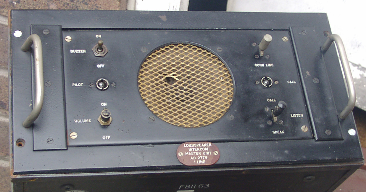
AD 2779 Loudspeaker Intercom Master Unit
(to be confirmed, possibly for Telebrief use)
When Telebrief is active, a relay in the aircraft disconnects the aircrews headsets from the aircraft radio and intercom system, and directly connects them to the external hardwired telephone connection for the briefing. The aircrew are purposefully disconnected from the aircraft systems, so that the ground crew plugged in under the wing can't hear the conversation, nor can it be accidentally transmitted via the radio.
While the aircrew's headsets are connected to the Telebrief system, the cockpit indicator switch illuminates, and pressing the switch connects their microphones to the system, similar to a "press to transmit" switch.
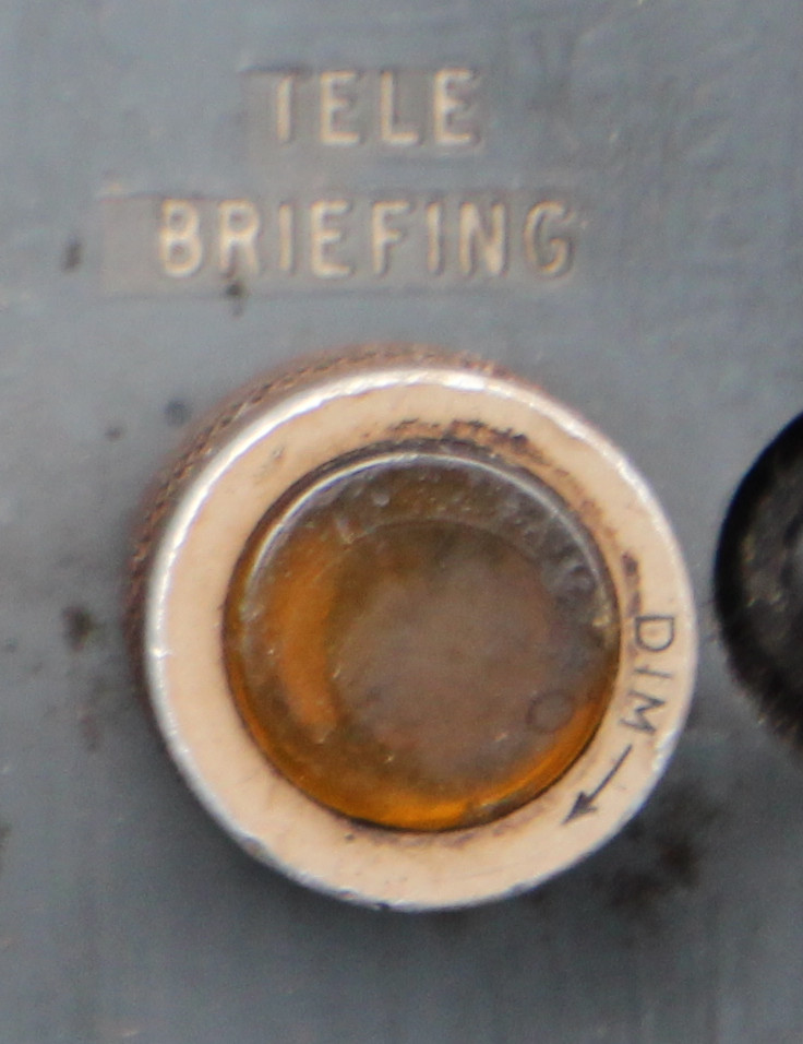
5CW/440022 telebrief switch on panel A3
Lightning T Mk. 5 XS458, 27-10-2018
It is a fairly robust Cold-War era method of keeping secrets, by only trusting the aircrew with the information, and reducing opportunities for it to leak externally.
PERSONAL EQUIPMENT CONNECTOR (P.E.C.)
The penultimate link in the chain is the aircrew connection to the system.
The aircrew each use a P.E.C. (Personal Equipment connector), which provides them with 4x essential services, and is also means of automatic disconnection from the aircraft upon ejection, and the seat upon separation during parachute descent.
REFERENCES
T Mk.5 electrical "Vol. 1":
A.P.101B-1005-1B, Sect.8, Chap.1, A.L.66, Sept. 1975 - U.H.F./V.H.F., Intercommunication and Telebriefing
F Mk. 3, T Mk. 5 and F Mk. 6 aircrew manual:
A.P.101B-1003, 5 & 6A, Part 1, Chapter 13, A.L.2, Nov 84, Communications Equipment
T Mk. 5 wiring diagrams:
AP101B-1005-10, Sheet 51, A.L.3, Nov 1981, VHF, UHF, Intercommunication and Telebriefing
AP101B-1005-10, Sheet 55, A.L.3, Nov 1981, VHF, UHF, Intercommunication and Telebriefing
F Mk. 53 and T Mk. 55 BAC Warton course notes:
BAC Avionics and Communication Systems, Course Notes, Section 4, Violet Picture Homer
WANTED
The following AP manuals would help in fully understanding the systems:
AP116B-0301 - U.H.F. Homing installations (A.R.I.18120)
AP116N-0301 - Telebriefing (A.R.I.18012 and F.G.R.I.18013)