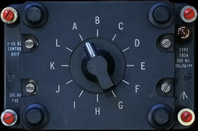
I.L.S CONTROL UNIT TYPE 705A
LEADING PARTICULARS
| Stores Ref. No.: | 10L/4704227 |
| Manufacturer: | Standard Telephones and Cables (STC) |
| Attachment: | Captive screws |
| Connection: | 104 Pattern / Plessey Mk. 4, small body 6 way; and 2x RF coaxial |
| Installation: | A.R.I. 18011 |
| System: | I.L.S. |
DESCRIPTION
The control unit can set the I.L.S. receivers to 12 different channels, or frequencies, to suit 12 different runways.
This unit is 'programmed' using pairs of crystals to set 12 different glidepath and localiser frequencies of the instrument landing system. In the T Mk.5 and 55, cards slotted into small perspex pockets would present a reference between letters and frequencies.
SIMULATION
ILS is modelled within Flightgear, so it may well be possible to utilise this control unit.
Unfortunately taking simple channel switching information isn't all that easy with this control unit. Each channel selection introduces a different pair of crystals to two RF circuits within the control unit. These circuits connect to the glidepath and localiser receiver units by a coaxial RF cable and form part of the tuning arrangement. The circuits within the control unit include various capacitors, inductors, transformers, and a thermionic valve (tube) each. So to simulate this interface, a fairly complex RF interface circuit would be needed with high voltage supply for the thermionic valves, plus I'd need to invest in a collection of crystals as this unit is empty... a bit over-the-top just to read the selector position.
Preservation vs. Modification - The Dilemma
This project's fundamental aim has always been to preserve the equipment without modification. However sadly in this instance, it's possible but just not practical, nor cost or time effective.
Minimalist Modification
The selector switch shorts to ground the crystals not in use, and connects the in-use crystals pairs of to the two RF circuits (localiser and glidepath). Initially it was tempting to add 12 wires to the 12 positions by soldering to the backs of the crystal sockets, however a better idea came about.
I placed different value resistors in each of the crystal sockets, giving the connection to the RF circuits a different resistance value to ground for each channel selection. This is used with an external resistro to a 5V supply to form a potential divider, which produces a stepped voltage level depending on channel selection. Using a single analogue Arduino input, this voltage level is measured and decoded into channel letters, passed to Flightgear and used for ILS channel selection.
Experiment No. 1
Note, this early experiment was with the earlier Type 705 unit before a Type 705A was donated, however, the learning gained from this experiement is easliy applied to the later type 705A.
Really pleasing results, the ILS channel letters appearing in the Flightgear property tree just as expected:
(You may need to go full-screen to see the on-screen character changing.)
REFERENCES
T Mk.5 electrical "Vol. 1":
AP4700E, Vol.1, Book 2, Sect.8, Chap.2, A.L.1, Nov 64 - Paragraph 5
T Mk. 5 wiring diagrams:
AP101B-1005-10, Sheet 37, A.L.3, Nov 1981, Cabin Lighting, Starboard
AP101B-1005-10, Sheet 55, A.L.3, Nov 1981, VHF, UHF, Intercommunication and Telebriefing
AP101B-1005-10, Sheet 56, A.L.3, Nov 1981, Radio and Radar Installations - Fig 2, I.L.S.
Flying, Aircraft and Equipment:
AP129, Volume 1, Part 2, Section 4, Chapter 1, August 1954, I.L.S..