CONNECTOR, PERSONAL EQUIPMENT (P.E.C.), BOTTOM (AIRCRAFT) PORTION
LEADING PARTICULARS
| Stores Ref. No.: | 27L/1290 |
| Manufacturer: | Martin Baker |
| Manufacturer P/N: | MBEU 8912 |
| Systems: | Oxygen & VHF/UHF, intercom and telebriefing |
DESCRIPTION
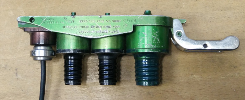
The bottom, or aircraft portion of the P.E.C. (personal equipment connector) connects personal services to the seat portion of the P.E.C. This connector automatically disconnects from the seat portion and remains in the aircraft upon ejection.
This particular type of aircraft portion P.E.C. (with three gaseous service ports) is not actually used by the T Mk. 5 or 55 aircraft, but is used by the T Mk. 4 and all single seat Lightning aircraft, they have been used in this simulator simply as they are more readily available. The T Mk. 5 and 55 used the uncommon seat mounted oxygen regulator system as noted in the oxygen system page, and use an aircraft portion with two gaseous service ports.
SIMULATION
For the simulator, these connectors are being used to bring headset mic/tel electrical connections from the simulator audio circuits to P.E.C. seat portions.
As one connector per seat are used, two are used by this simulator project.
RESTORATION
Both of the connectors acquired for this project had no hoses, and the communications cables were cut off at the gland nuts. This gave opportunity to wire them in a manner to suit the simulator project.

Two aircraft portion PECs, as acquired
DISMANTLING
The most difficult part of dismantling these connectors was unscrewing the mic/tel cable gland nut as thread locking is used during assembly.
The glad nut has no flats, instead is drilled with 4 1/8" holes for a special C spanner. Not having access to a special C spanner, I made my own tool using some stiff steel wire of a suitable diameter.

Improvised PEC mic/tel cable gland nut spanner
Releasing the nut involved applying heat with a hot air gun to soften the thread locking compound. As the gland nut is made from an ordinary stainless steel, there is only so much force that can be applied to the small holes before they start to deform - the heat really helps to free the gland nut off.

PEC mic/tel cable gland removed, cable sheath stuck in gland
Note was taken of which terminals have which colour wires landed on them.

Noting which colour wires land on which terminals
CABLE PREPARATION
I used cables that had been cut from RACAL "Atlantic" headsets, these are nice quality, robust, and came with a factory fitted type 671 plug ("NATO Plug") which can be used to connect to the simulator audio circuits. Being headset cables, they also have screens applied only to the two microphone wires, as per the original cables.
As the cable was a "tinsel" type of construction (similar to the original cable, just finer), this cannot be directly soldered. If suitable tiny crimps and tools are available it can be crimped, and these soldered, but alternatively the old-fashioned fiddly method of lashing the bared conductor with thin copper wire works well, but only if you have the patience for applying it!
Tinsel cable: Tiny flat stands of copper are wrapped around a central cord. Several of these wrapped cords are then wound around another larger diameter cord to form the conductor, this is then insulated. Complex, fiddly, likely quite expensive, but very flexible.

Prepared cable, with gland components
As this cable was of a smaller sheath diameter than the original, some adhesive lined heat-shrink sleeving was applied to the end to make up the thickness so the gland rubber bush was able to grip the cable adequately.
ASSEMBLY
The insulation colour code of wiring used in RACAL headsets does not comply with the original Def-Stan colour codes, conversion table shown below:
| Purpose | Def-Stan Core Number | Def-Stan Colour | RACAL Colour |
|---|---|---|---|
| Tel + | 1 | Red | White |
| Tel - | 2 | Blue | Orange |
| Mic - | 3 | Green | Green |
| Mic + | 4 | Yellow | Red |
After soldering the new wires in place, the gland body was re-fitted to the PEC, and gland re-assembled and tightened using the improvised spanner.

New cable soldered in place
The two aircraft portion PECs shown, fitted with short leads and type 671 "NATO" plugs for convenient connection to the simulator audio circuits.

The two PEC aircraft portions completed
REFERENCES
Aircrew Equipment Assemblies:
A.P.1182, Sect. 1, Chap. 5, A.L.30, Oct. 1959 - Personal Equipment Connector