UNDERCARRIAGE INDICATOR TYPE D1
LEADING PARTICULARS
| Stores Ref. No.: | 5CZ/5164 |
| Manufacturer: | Dowty |
| Attachment: | 28D/1213898 | AS.3295/4B | Bolt, 4 BA, phillips recess |
| [or] | |
| Attachment: | 28S/9128947 | A204/B24 | Screw, No. 6 UNC c'sk head |
| Connection: | Screw terminals |
DESCRIPTION
The Type D1 undercarriage indicator was used in all Mk's of Lightning, and similar versions were also used in other aircraft.
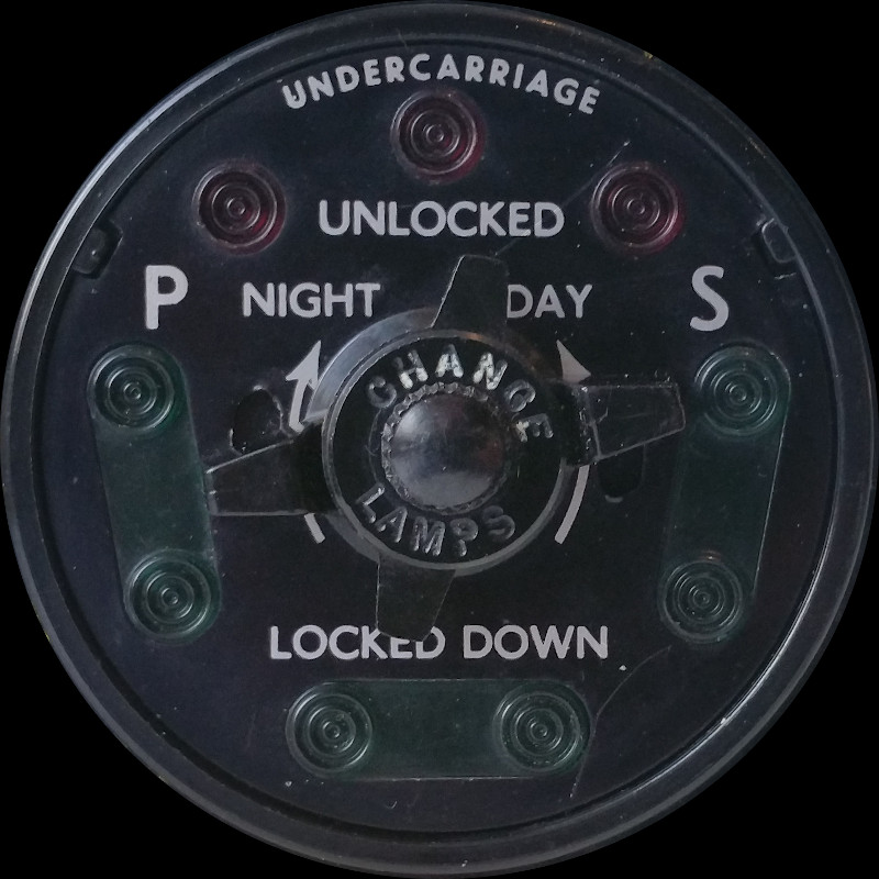
Three lamps are installed behind red filters for undercarriage "UNLOCKED" indication, and two sets of three lamps are behind green filters for undercarriage "LOCKED DOWN" indication. The "CHANGE LAMPS" selector switch on the front selects between the sets of green lamps (in case of filament failure), and a further "NIGHT / DAY" selector moves a smoked filter in front of the lamps internally to dim them. The very small central knob unscrews the facia for lamp change.
The Lightning T Mk.5 and T Mk.55 used two of these indicators, simply wired in parallel, one for instructor (stbd), one for student (port).

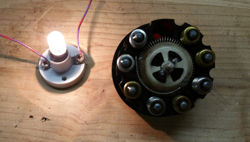
The facia contains the lamps, held in place by a spring that also acts as the common ground connection.
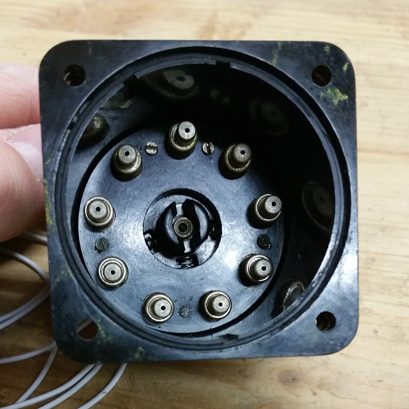
The body holds sprung terminals for each lamp end contact. The switch for changing over the green "LOCKED DOWN" lamp set is in the body behind the sprung terminals, and is acted upon by a central shaft from the facia selector.
LAMPS
The history of this indicator is unknown, so I am not assuming its lamp configuration to be correct. It came with a mix of lamps installed made by OSRAM↗ and THORN↗.
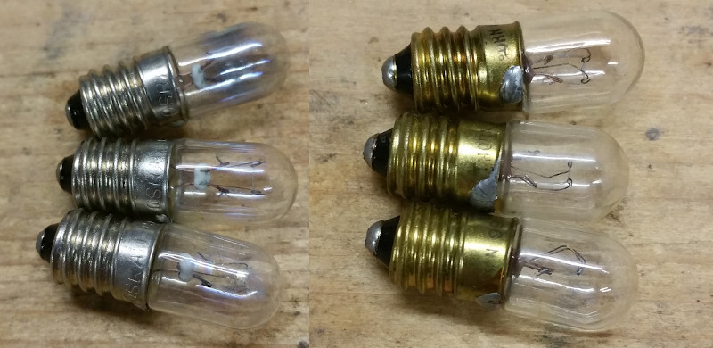
More importantly, I found a mix of 995-1286 and 995-1284 part numbers marked on the lamps, relating to different Wattages. Looking online, these were found to be parts of NATO stock numbers, preceded by "6240-99-".
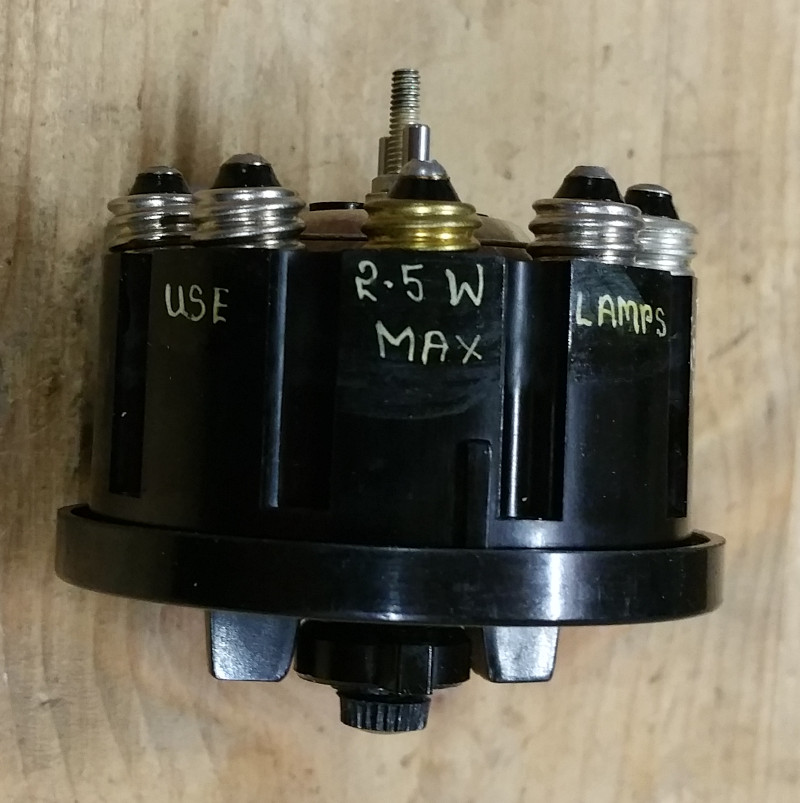
A big clue about which lamps were correct for use was found inscribed on the facia: "USE 2.5W MAX LAMPS".
To to determine the correct lamp of the two types I tested them at 28V, measured their currents and calculated their Wattages:
6240-99-995-1286 = 2.5W (measured and calculated)
6240-99-995-1284 = 3.25W (measured and calculated)
The 6240-99-995-1286 appears to be the most suitable lamp for this indicator (of the two types examined) based on the MAX Wattage stated.
Looking online, I determined the lamps have an E10 base, with a T1 1/4 Clear bulb, such as this↗ industrial version from RS components.
LAMP CONFIRMATION
A while after this detective work, I stumbled across a paragraph (No. 17) in the alighting gear section of the electrical "Vol. 1" (linked below) that the recommended lamp Stores Ref. No. is 5LX/951286, which aligns neatly with the modern NATO stock number 6240-99-995-1286. The text also states 28V, 2.5W, agreeing with the pained lettering on the indicator. This paragraph confirmed my reverse engineering to be correct!
CIRCUIT DIAGRAM
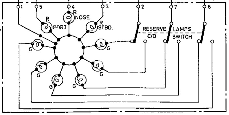
Internals of the Type D1 undercarriage position indicator from AP101B-1005-10, Sheet 20:
SIMULATION
As the Arduino boards can only output either 3.3Vdc or 5Vdc depending on the model, an interface circuit is required to provide 28Vdc to the lamps. Each lamp draws around 90mA, which also exceeds the current limit of most Arduino I/O pins.
Some form of driver circuit is required.There are many ways to skin a cat, but I wanted to avoid using relays as:
- They are big, and there would be one per lamp.
- They still would require some transistorised drive circuit for the relay coil.
- The coil would give us back-emf to deal with.
- They produce unwanted clicking sounds when the lamps changed.
A neater solution is to use transistors instead. A colleague mentioned to me about an even neater solution, a transistor array package. He recommended I looked into the ULN2003 series of Darlington transistor arrays, which come conveniently in a 16 pin DIL package. The ULN2003A is capable of providing up to 50Vdc, up to 500mA per Darlington transistor, and there are 7 transistors per package (I need 6). To turn on the Darlignton transistor a voltage between 2V and 13V is needed so the Arduino outputs of either 3.3V or 5V fit perfectly within this range.
For this method to work, we need to reverse the polarity of the indicator as the ULN2003A is designed to switch to ground. So terminal 1 which in the aircraft would be used for ground connection, is now to be connected to +28Vdc; and the Darlington transistors switch the individual lamp terminals (2,3,4,5,6,7) to ground.
This simulator uses two undercarriage indicators, and as each transistor is capable of delivering 500mA, two 90mA lamps connected in parallel giving a total of 180mA should be within the capabilities of this device.
Experiment No. 1
The ULN2003 Darlington transistor array worked beautifully in driving the lamps of this indicator, they were very bight and responded instantly to inputs. The lamps were fed by 24Vdc on terminal 1 of the indicator, and the transistors successfully switched the lamps on / off when the bases were tested at both 3V and 5V.
Experiment No. 2
For this test, I added an MCP23008 I²C I/O expander chip so I could sit the indicator on an I²C network, saving I/O pins of the Arduino. The I/O expander outputs directly connect to inputs of the ULN2003. A very Heath Robinson prototype setup was thrown together to test the theory:
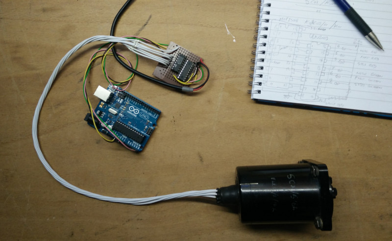
Utilising the Adafruit MCP library, I put together a very simple Arduino program which flashes the lamps in sequence, just to test if the hardware worked.
This video is the result of this experiment:
(Notice how one of the port green lamps is not working, demonstrated by the "Change Lamps" switch.)
At 5V logic supply, the base current of the ULN2003 was about 1.3mA, which is well within the 25mA capabilities of the MCP23008 I/O expander outputs. The lamps drew about 85mA each from the ULN2003 Darlington transistor array when supplied with 24V, again, well within the 500mA maximum rating of the ULN2003 outputs.
I also discovered how tempremental I²C can be if a wire is loose, or interferance is picked up; it can cause the MCP23008 to miss commands - so in this experiment I found that a lamp may stay on for a cycle until it's next told to go off. And another thing, some I²C glitches casue the Arduino to crash, this is using the Adafruit MCP library, but a little research online show alternative libraries which may negate this issue. In this experiment I did not add pullup resistors to the SDA and SCL wires as the Arduino internaly provides these, however, this may have helped.
One of my aims for this simulator (as a whole) is to utilise I²C networking between the master controller and slave boards operating indicators, so this is a first step in the right direction of a modular design, but first I need to find reliable wiring methods.
REFERENCES
Indicator general and technical information:
AP4343E, Volume 1, Book 4, Section 18, A.L.233, July 1964, Undercarriage Indicators, Dowty 1224Y Series
T Mk. 5 electrical "Vol. 1":
AP101B-1005-1B, Section 6, Chapter 5, A.L.54, June 1973, Alighting Gear and Brake Parachute - Paragraph 6
T Mk. 5 wiring diagrams:
AP101B-1005-10, Sheet 20, A.L.5, Dec. 1984, Alighting Gear
ULN2003A datasheet:
Texas Instruments SLRS027P Aug. 2019, ULN2003A Darlington Array
MCP23008 datasheet:
Microchip DS20001919F 2019, MCP23008 I²C I/O Expander