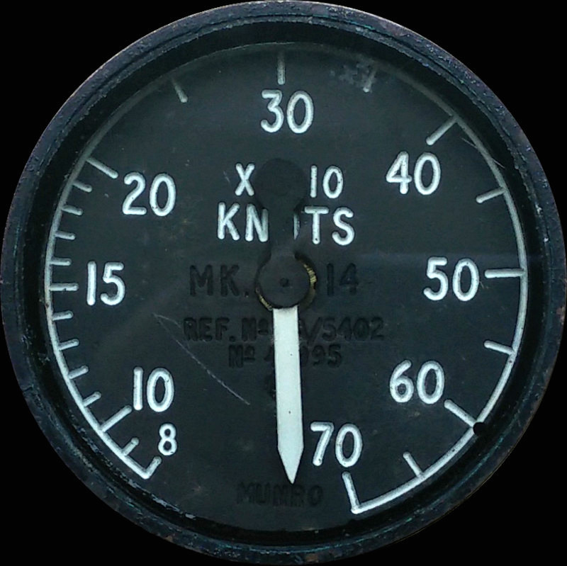
STANDBY AIR SPEED INDICATOR Mk. 14
LEADING PARTICULARS
| Stores Ref. No.: | 6A/5402 |
| Manufacturer: | Munro |
| Manufacturer P/N: | AS/10A/303 |
| Connection: | Air hose / clamp |
| Attachment: | Clamp, instrument securing type C.12956 |
DESCRIPTION
The standby air speed indicator (ASI) acts as a standby to the main ASI in case of failure. The main ASI relies on 400Hz AC power to work, so can be comprimised by elelctrical issues. The standby ASI is purely mechanically / pneumatically operated by pitot static air pressure so will survive a power issue.
VERSIONS
The Mk. 14 and Mk. 18 standby air speed indicators are practically identical, however the Mk. 18 has a larger diameter fitting for the static pressure hose. So far I have found that the aircrew manual for the F Mk. 3, 6, and T Mk. 5 states a Mk. 14 is used, and the T Mk. 55 IPC shows the Mk. 18 version. For the sake of the simulator, either will be fine!
SIMULATION
The only way to simulate this indicator without modification is to invent a pressure control system to simulate atmospheric pitot static air pressure at altitude, and ram air pressure depending on air speed. While this is not a walk in the park, and probably many years away, it will also serve to provide static pressure to the standby altimeter too.
REFERENCES
Indicator general and technical information (Mk. 14):
A.P.1275a, Volume 1, Section 21, Chapter 20, A.L.24, Sept. 1958 - Standby Air Speed Indicator, Mk14
Indicator general and technical information (Mk. 14 and Mk. 18):
A.P.112G-0939-1, A.L.1, Jan. 1974 - Standby Air Speed Indicators, Mk. 14 and Mk. 18
T Mk.5 electrical "Vol. 1":
A.P.101B-1005-1B, Sect. 7, Chap. 5, A.L.60 Nov 1973, Flight Instruments - Paragraph 15
F Mk. 3, T Mk. 5 and F Mk. 6 aircrew manual:
A.P.101B-1003, 5 & 6A, Part 1, Chapter 7, A.L.2, Nov. 1984 - Instruments - Paragraph 43