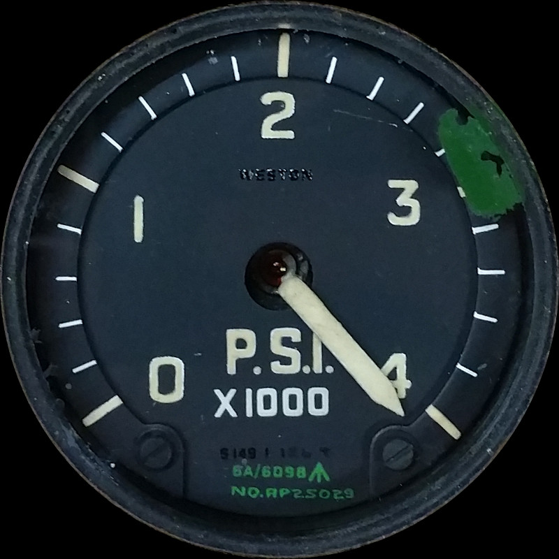
WHEEL BRAKE PRESSURE INDICATOR TYPE S149.1.126
LEADING PARTICULARS
| Stores Ref. No.: | 6A/6098 (and later 6A/4338317) |
| Manufacturer: | SANGAMO WESTON |
| Attachment: | Clamp, instrument securing type C.12956 |
| Connection: | UK-AN / MIL-C-5015, 3 way |
DESCRIPTION
This indicator is a ratiometer type of indicator, fed from a single brake pressure transmitter.
It will operate when DC power is online.
Note: latter Stores Ref. No. 6A/4338317 found in A.P.112G-0508-1 2nd edition, dated 1990.
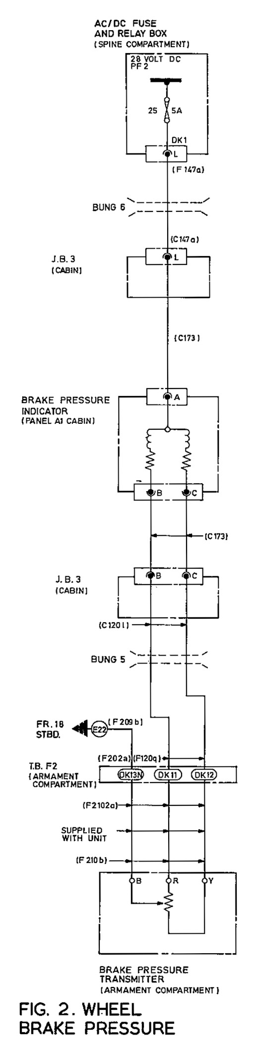
CIRCUIT DIAGRAM
The internals of the transmitter and indicator illustrated, and interconnecting wiring taken from AP101B-1005-10 Sheet 130, A.L.3, Nov. 1981.
SIMULATION
Being a ratiometer, its two coils need energising to make it operate. The indicator is marked 24V, and the aircraft installation provides it with 28V dc, But, as it's an indicator that should still work with a lower voltage, there was a chance it may work directly powered by an Arduino output or two. There is a spring inside the indicator which tries to pull the pointer up to max (rest position with no power is 4000psi) so the effort of the coils is to pull the pointer down.
These coils in normal operation receive the opposite current, such that when coil A is at low current, coil B will be at high current; and vice versa.
Experiment No. 1
To save on I/O count, I had the idea to set a permanent current flowing through a resistor in one coil to about 50% of max current flow, then drive the other coil with an Arduino 3.3V output between 0mA and max mA via a resistor and smoothing capacitor to result in DC. This did work to an extent, but the low voltage led to low torque and the pointer found it hard to overcome stiction, which led to significant hysterisis.
Experiment No. 2
As using one output wasn't terribly successful, I tried using two outputs, and in the Arduino softwre set the second one to to exactly the opposite of the first one, representing the potentiometer in the aircraft pressure transmitter. This meant also adding another capacitor to smooth the second output to DC.
This second method worked better than the first, at the sacrifice of another I/O pin. This method increases the ratio of the magnetic field strengths, and increased shaft torque to overcome stiction, all on 3.3v from the arduino board. I imagine a 5V arduino like the UNO would be able to drive it witha little more grunt too.
I found that you can't use a full range right down to minimum current; the indicator is designed so that both coils need to maintain a minimum amount of field strength in order to give the other coil something to work against. Initially I have achieved this by just limiting the output of the Arduino, at the sacrifice of resolution (255 steps are now about 100) but I'm sure this could be achieved with a small network of reisistors to maintain minimum current and allow the arduino to pull each side up and down, using the full resolution of 255 steps.
Even with limited resolution for the experiment it still operated quite smoothly, see video:
RESULT
I created the hydraulic system model for the FGUK T5 and hey-presto, it worked roughly as it should do in the real aircraft! I set the minimum pressure to 1700psi as this pressure would typically be retained in the accumulator if the aircraft was recently flown or engines run, then the pressure follows engine speed up to 3000psi.
REFERENCES
Indicator A.P.:
A.P.112G-0508-1, Chap.2-5, Feb. 93 -S149-1-126 Indicator
Sangamo Weston Manual:
Electrical Instruments For Aircraft, Section 0 - Prelim
Electrical Instruments For Aircraft, Section 6 - Presure Indicators
F Mk. 3, T Mk. 5 and F Mk. 6 aircrew manual:
A.P.101B-1003, 5 & 6A, Part 1, Chapter 6, A.L.2, Nov 84 - Other Aircraft Controls - Paragraph 25
T Mk.5 electrical "Vol. 1":
A.P.101B-1005-1B, Sect.7, Chap.6, A.L.62, Feb. 1974 - Miscellaneous Instruments - Paragraph 8
T Mk.5 wiring diagrams:
AP101B-1005-10 Sheet 130, A.L.3, Nov. 1981 - Miscellaneous Instruments
SIDE NOTE
It's worth being aware that most Mk's of Lightning used the S149.1.126 single reading brake pressure indicator, but I have found evidence from 1974 (in the electrical Vol 1), under mod 4212 (ref aircrew manual) that a triple indicator type S214.1.45 was fitted to the F6, and two extra transmitters were added in the main wheel wells to read the individual brake supply pressures in addition to the accumulator pressure. Pre-mod F Mk. 6 aircraft used the same indicator as the F Mk. 3 and T Mk. 5. The T Mk. 55 IPC only details this same single reading indicator.