(Example image from XS458)
WANTED:
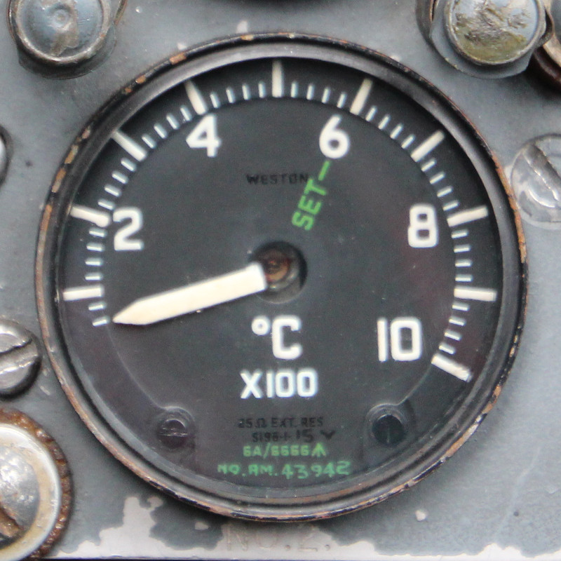
JET PIPE TEMPERATURE INDICATOR TYPE S196-1-15
LEADING PARTICULARS
| Stores Ref. No.: | 6A/6666 |
| Manufacturer: | Sangamo Weston |
| Attachment: | Clamp, instrument securing type C.12956 |
| Connection: | Screw terminals |
DESCRIPTION
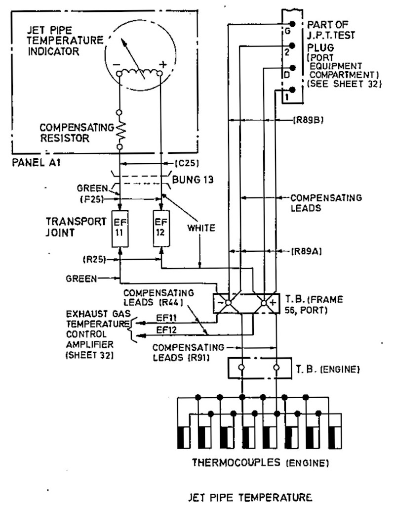
These indicators are conencted to a ring of 8 thermocouples arranged around the engine exhaust duct. The thermocouples are connected in parallel in order to give a single averaged temperature reading of the engine exhaust gas. The Seebeck effect↗ of the bi-metal thermocouples generates a small electrical current proportional to temperature, these indicators are designed so that the pointer can be operated directly by this small current, with no need for any additional power supply or control circuitry. The "cold junction" is contained within the indicator casing. The thermocouples are Type K, Alumel and Chromel.
In the Lightning there is a protection circuit (the exhaust gas temperature control amplifier) that monitors the thermocouple current; if the top temperature limit is reached a solenoid valve in the engine's FCU (fuel control unit) is tripped, limiting the engine's fuel supply to reduce power and temperature. The pilot does have a pair of override switches to disable this protection if the extra power is needed, at the potential sacrifice of the engine turbine and jet pipe metalwork. This circuit simply monitors the voltage across the thermocouple wires, and inputs nothing to drive the cockpit indicators.
CIRCUIT DIAGRAM
T5 Lightning circuit diagram - edited drawing taken from A.P.101B-1005-10, Sheet 35, Fig.1, A.L.3, Nov. 1981.
SIMULATION
In absence of the correct indicators, I have been experimenting with a pair of Buccaneer T.G.T. indicators.
Using a pulse width modulated "PWM" output of the Arduino, I passed this signal through a resistor and capacitor "R/C" network to smooth it to a variable DC level, and connected to the indicator.
I am purposefully witholding the component values as I don't yet have the correct indicators to test the circuit on, but I have been experimenting on a fairly similar pair of Buccaneer T.G.T indicators to prove the theory.
DAMPING OVERSHOOT AND RINGING
This was quite an interesting part of the experiment. If these indicators are given a step change in current, the pointers tend to overshoot, followed by "ringing" until the pointer settles down at the desired position after a few seconds. In figuring out this issue I realised that when the pointer swings, so does the moving coil inside the indicator, and a coil moving in a magnetic field acts as a generator. So if the unwanted overshoot and ringing has the potential to generate some current, by giving the "generator" an electrical load, this load will be transferred to a physical torque load, making it harder for the pointer to move fast.
These indicators state on their faces that an external resistance of 25Ω is required, and this was backed up by the data sheet (see below). This external resistance is achieved in the aircraft by adding a wire-wound bobbin / spool to the back of the indicators in series with the low impedance thermocouples to increase the total circuit resistance to 25Ω.
As I am not using a low impedance source, instead a high impedance Arduino output and RC smoothing circuit, I added resistor directly across the indicator terminals, and this fixed the overshoot and ringing instantly.
As the indicator resistance is about 30Ω, adding a 25Ω resistor in parallel would have roughly halved the terminal resistance, so I would have needed to roughly halve the resistance of the series resistor in the RC circuit in order to drive roughly double the current. While double the current was still within the capabilities of the Arduino output, I didn't want to add excessive load to the Arduino. So I tried a few combinations and settled with a 41Ω resistror across the terminals, which still provided enough damping effect, without lowering the terminal resistance too far, keeping the Arduino output current as low as possible.
Adding this resistor has made a massive difference to how these indicators perform, giving a really smooth opeation by sinking the current generated by overshooting upon a step change.
Here's the result of using a resistor for damping the Buccaneer T.G.T. indicators, the first video shows a direct comparison of damped with resistor, and under-damped without resistor. The second video shows nice damping of big step changes with both resistors in place.
Before:
After:
WANTED
I am in need of two Lightning JPT/EGT indicators, Type S196-1-15, 6A/6666.
REFERENCES
Indicator general and technical information:
A.P.112G-0605-1, Chapter 1-0, June 1966 - indicator type S196 series
A.P.112G-0605-1, Chapter 1-2, Dec 1984 - indicator type S196.1.15
Sangamo Weston Manual:
Electrical Instruments For Aircraft, Section 0 - Prelim
Electrical Instruments For Aircraft, Section 5 - Temperature Indicators
T Mk.5 electrical "Vol. 1":
AP101B-1005-1B, Section 7, Chapter 4, A.L.51, Nov. 1972, Engine Instruments - Paragraph 16
T Mk.5 wiring diagrams:
AP110B-1005-10, Sheet 35, Fig 1, A.L.3, Nov 1981