AUTOPILOT TRIM INDICATOR TYPE C
LEADING PARTICULARS
| Stores Ref. No.: | 6TD/709 |
| Manufacturer: | Elliott |
| Manufacturer P/N: | 3D/1135 |
| Connection: | Plessey Mk.4, 6-way |
DESCRIPTION
A full picture of how this indicator works / what ot displays is yet to be found, but scraps of evidence have so far given the following picture.
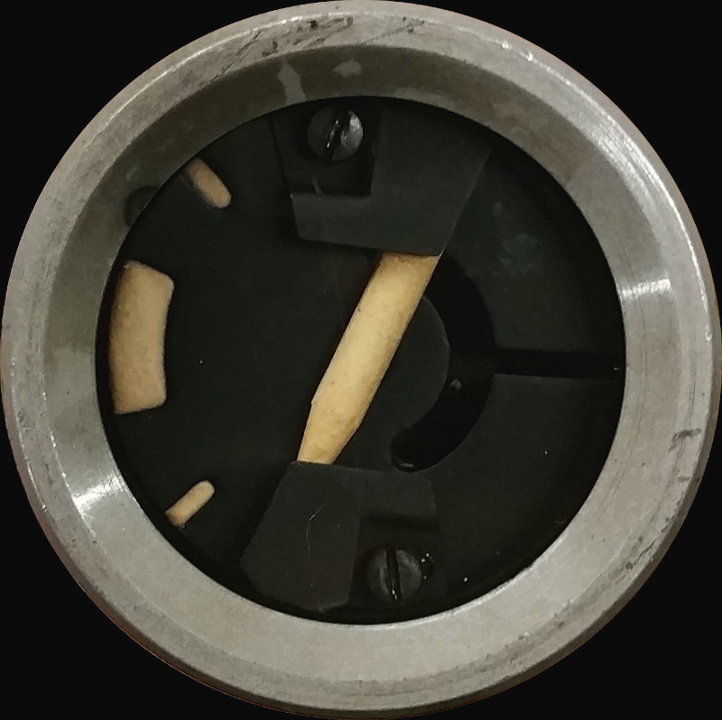
This indicator reveals trim effort being applied by the autostabiliser actuator. It shows that if the FCS Engage switch is moved to "OFF", the the aircraft will pitch in the direction shown by the indicator, and will require manually trimming back. More information is documented in the aircrew manual below, as various modes of the FCS have different effects on the indication.
I believe that this indicator shows error between the autopilot elevator angle demand, and feedback of the elevator angle as it is connected directly to the flight control computer and the auto trim amplifier.
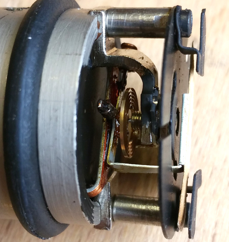
Internally it is another watchmaker's masterpiece. It uses a delicate moving coil and permanent magnet, and a light watch-spring to operate the pointer.
SIMULATION
The circuit diagrams in the Vol 1 (below) show 4 connections to this indicator, however, I can only find 3 connected internally, and testing the resistance of them, the indicator appears to have two coils wound in series with a centre tap, or looking at it another way, one common ground and two coils, making this akin to a ratiometer.
Experiment No. 1
As described above I didn't quite know what to expect of this indicator as information is sketchy, however through this experiemnt I believe I've cracked it:
It takes signals from the flight control computer and the auto trim amplifier, so I simulated these signal using two potentiometers and a DC supply, giving two variable DC currents, one to each coil.
I found that both coils could indeed operate the pointer across it's full scale deflection independently of the other. Meaning that if the flight control computer and the auto trim amplifier supply similar opposing signals; the pointer should stay roughtly central, but if the computer demands a change that is not met, the pointer will progress off-centre, either up or down depending on the nature of the fault.
This theory is not proven, but is my best deduction based on the circuit diagram, description and my own testing work, showing that this is how the coils operate the pointer.
The video below shows the pointer being moved by adjusting a potentiometer on a DC supply.
WANTED
Any information on the Elliott Flight Control System (FCS) such as APs or manufacturers manuals please. These will hopefully help me to understand exactly how this indicator works, so I can simulate it with some accuracy. If you can help, please see the contact page.
REFERENCES
F Mk. 3, T Mk. 5 & F Mk. 6 aircrew manual:
AP101B-1003, 5 and 6-15A, Part1, Chapter 8, A.L.2, Nov. 1984, Flight Control System - Paragraph 24
T Mk. 5 wiring diagrams:
AP101B-1005-10, Sheet 123, A.L.3, Nov. 1981, Flight Control System (Strip 4)
T Mk.5 electrical "Vol 1":
AP101B-1005-1B, Section 7, Chapter 3D, A.L.12, Mar. 1965, Flight Control System - Paragraph 9
T Mk.5 electrical "Vol 1":
AP101B-1005-1B, Section 7, Chapter 3D, A.L.12, Mar. 1965, Flight Control System - Figure 8