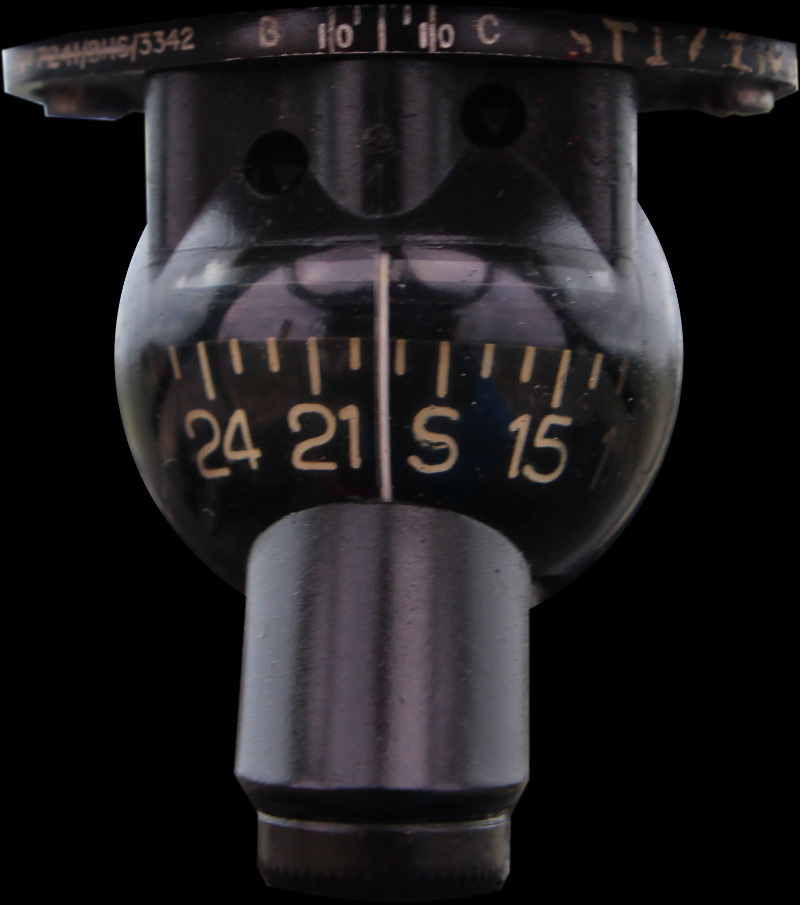
SIMULATOR STANDBY COMPASS (MODIFIED TYPE E2B)
LEADING PARTICULARS
| Part. No.: | 964641 |
| Manufacturer: | Original parts Kelvin & Hughes (under Smiths) - Modified by Unknown |
| Attachments: | 28D/1212964 | A61/1B | Bolt, 4BA hex. head, Light Alloy | Qty: 2 |
| Attachments: | 28M/1956039 | AGS.2001/B/3 | Nut, stiff, 4BA, Light Alloy | Qty: 2 |
| Connection: | 6B/2755 | CE2/A26 | Lead and Socket Assembly (5ft.) & Solder turrets for control connections |
ALTERNATIVE PART
This simulated compass is being used in place of a real type E2B compass, page here: type E2B compass.
DESCRIPTION
A regular E2B, but modified for simulator use with the addition of a Desynn positioner. This removes the original top plate corrector adjustment assembly, and is replaced by a mounting plate for the Desynn positioner.
The rear bellows are removed, and replaced with a Bakelite disk, fitted with three solder turrets for connection to the Desynn positioner coils. The internal wiring passes from the turrets, through a hole drilled in the top of the bowl, and into a top cap to the Desynn positioner coils.
The bowl is not liquid filled as there are drillings in this modified example which does make the card appear smaller. A filled bowl acts as a convex lens, or a magnifying glass, making the card more prominent. But when the special silicone oil costs about £50, it's no great loss.
SIMULATION
After checking the coil DC resistance, I connected a Desynn position transmitter to the compass, and initially tested it with 9 V, just to limit the current in case of an issue, the compass card moved slightly, when power was applied and when the transmitter was moved - a good sign.
Experiment No. 1
Once confident the preliminary checks didn't reveal an issue, I connected a 24 V DC power supply to the Desynn transmitter, and the compass sprang into life!
The slightly jittery motion is just due to my hands operating the transmitter, it should be much smoother when driven by simulator data.
REFERENCES
Smiths literature:
34-04-70-DM, 29-11-1957, Maintenance Manual E2 Series Compasses
Smiths Leaflet C2-1, E2 Series Compass
Kelvin & Huhges / Smiths E2 Sereis Compasses (1957):
SP514, Issue 2, March 1957, Spare Parts List
E2 Series Compass General and Technical Informaion (1957):
AP1275B, Vol 1, Sect 10, April 1957, Compasses, Magnetic, E2 Types (Note: Fig 1 erroneously shows E2B)
E2 Series Compass General and Technical Informaion (1990):
AP112B-0201-13A, Amdt 15, Feb 1990, Compass Standby Magnetic
E2 Series Compass General Orders and Modifications (1990):
AP112B-0201-2, 1st Edition, Feb 1990, Compass Standby Magnetic
Flying, Aircraft and Equipment (circa 1950's):
AP129, Volume 1, Part 2, Section 3, Chapter 4, Self Contained Magnetic Compasses
Standard Technical Training Notes - Compasses (1968):
AP3280A, Section 3, Chapter 1, A.L.32, Oct 1968, STTN Compass Adjustment
F Mk. 3, T Mk. 5 and F Mk. 6 aircrew manual:
A.P.101B-1003, 5 & 6A, Part 1, Chapter 7, A.L.2, Nov 1984 - Instruments - Paragraph 51
T Mk.5 Electrical "Vol. 1":
AP101B-1005-1B, Section 7, Chapter 5, A.L. 60, October 1973 - Flight Instruments - Paragraph 11
T Mk.5 wiring diagrams:
AP101B-1005-10, Sheet 36, A.L.3, Nov 1981, Cabin Lighting, Port
AP101B-1005-10, Sheet 37, A.L.3, Nov 1981, Cabin Lighting, Starboard