DATA LINK
LEADING PARTICULARS
| A.R.I No.: | 18168 |
DESCRIPTION
The data link system was never operationally used. There are stories of it being flight tested, and the Lightning manuals all include some information on the equipment, but with "if fitted" clauses. The aircraft carried trays and mountings for the equipment, just in case it was ever to come into service.
This article talks about the system as if it was fitted, and how it would bring information to the pilot.
Linesman
The Lightning aircraft formed a part of the UK's wider air defense system, code name: "Linesman".
Linesman was put in place to detect an approaching airborne threat using ground radar stations at Gailes, Boulmer, Saxton Wold and Neatishead who would pass this radar data on to a central control point named "L1" at West Drayton, where specific targets could be allocated to specific Lightning aircraft. Once scrambled on QRA, the intercept controller could request the Lightning pilot to switch his radio (and navigation indicator) over to Data Link mode.
Ground data communication via telephone infrastructure used the Link 1 standard between radar stations and L1, and ground to air communication via UHF radio used the Link 4 standard.
When the aircraft is set up for Data Link mode, the intercept controller could direct the aircraft using coded binary messages transmitted over U.H.F. radio. This would result in information being presented to the pilot by the flight and navigation instruments, or by activating the flight control system (auto pilot) the aircraft could then actually be remotely directed without the pilot's input.
Incredible to think this was possible in a 1960s designed system.
An article in Flight magazine from 14 September 1961 talks about the telephone links used for ground-to-ground data links between radar stations using telephone lines, and then goes on to the ground-to-air side:
After conversion in the airborne data link unit from digital to analogue form the instructions to the aircraft can either be displayed on suitable instruments or coupled into the autopilot. Both ground and airborne units are fully transistorized and are designed for high reliability.
UHF Data Link Communications and Protocol
The extract below from a NATO standard for Data Link, Link4, defines some of the flight command signal messages to be passed to the aircraft, such as: altitiude, air speed, rate of descent. It has been confirmed to me (D.K.H.) that NATO's "Link 4" protocol was used as the protocol between ground intercept controller and the Lightning aircraft..
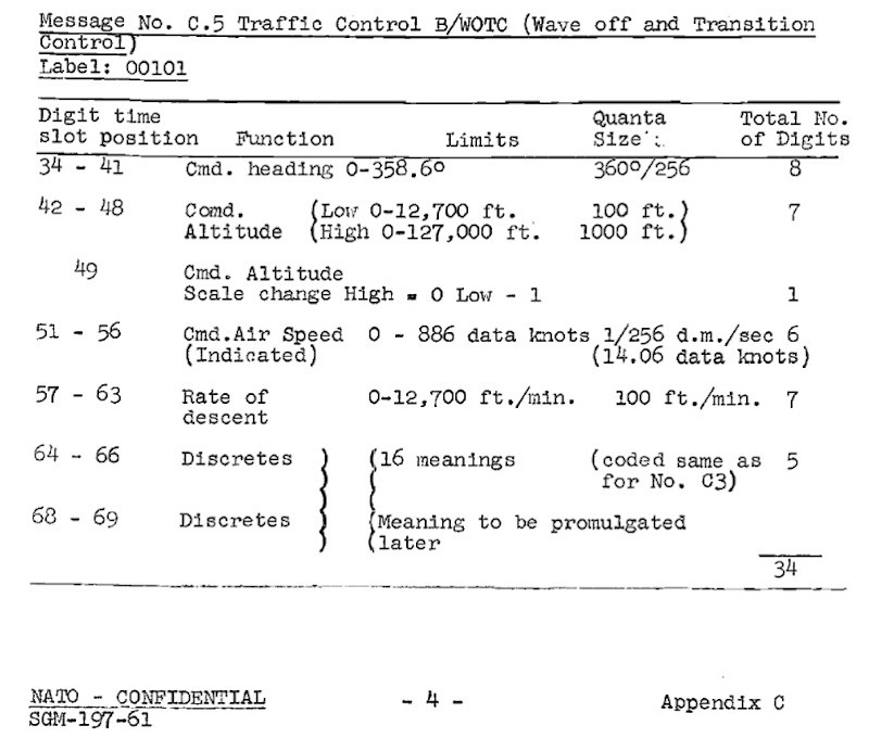
Extract from
NATO document SGM-197-61, Appendix C, Page 4, 1961
Standards for NATO Data Links: Link 4
As voice communication is disabled with the radio in DL mode, one important recorded voice command was "Return to RT" when the Data Link session is at an end.
In analysing the system, there appears to be two categories of information, "commands" for the airctaft being controlled, and "target" location information.
The physical method of passing this data was achieved though Frequency Shift Keying (FSK) the tranmitted U.H.F. signal by 20kHz. This is unusual as the radio systems use A.M. (Amplitude Modulation) for voice communications, and F.S.K. is a basic form of frequency modulation (F.M.), this required a special demodulator module to be used within the radio T/R unit.
SYSTEM USE
Assuming the required equipment is installed and configured, and the controlling ground radar station has provided a UHF frequency to use, Data Link is active when:
- The C1607 V.H.F. / U.H.F. control unit mode switch is set to DL (DL/T is a test mode)
- The C1607 V.H.F. / U.H.F. control unit frequency is set to the correct UHF frequency.
- The navigation display mode switch is set to DL.
The aircrew receive commands and target information from the Data Link system via:
- The air speed indicator displaying command speed.
- The navigation display displaying command bearing and range.
- The altimeter displaying command altitude and target altitude.
- Audio pre-recorded voice command messages played into the aircrew headsets.
REQUIRED EQUIPMENT
The specification agreed by NATO for Link 4 lists the aircraft systems a data link system should be interfaced with:
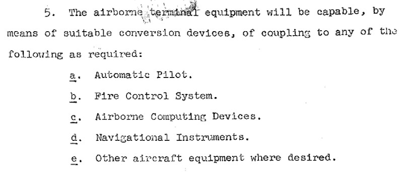
SGM-0229-62, 1962, Specification for Link 4
Enclosure 1, I General Information, Paragraph 5
Units requred for the Data Link system in the Lightning:
- Main VHF/UHF T/R Unit - Type PTR-177 (in lieu of voice-only PTR-175)
- Signal Data Converter - Type 11673
- Selector Address Unit - Type 11941
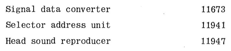
- Head Sound Reproducer - Type 11947 or 11974 (see discrepancy below)
Extract from: AP101B-1005-1A, Section 2, Chapter 3A, AL99, July 1980
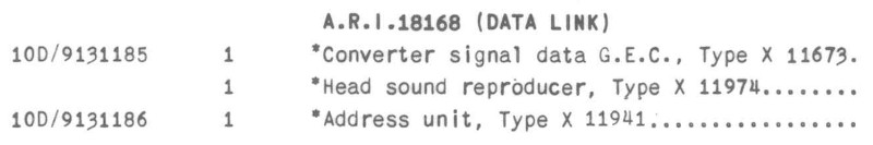
List of A.R.I. 18168 Data Link parts
Extract from: AP101B-1005-1B, Section 8, Chapter 1, AL60, Oct. 1973
List of A.R.I. 18168 Data Link parts
In addition to these units, a configuration change is needed: The C1607 control unit has a switch hidden round the back that also must be set to DL or G depending on the installed hardware configuration (DL for Data Link demodulator, or G for Guard receiver).
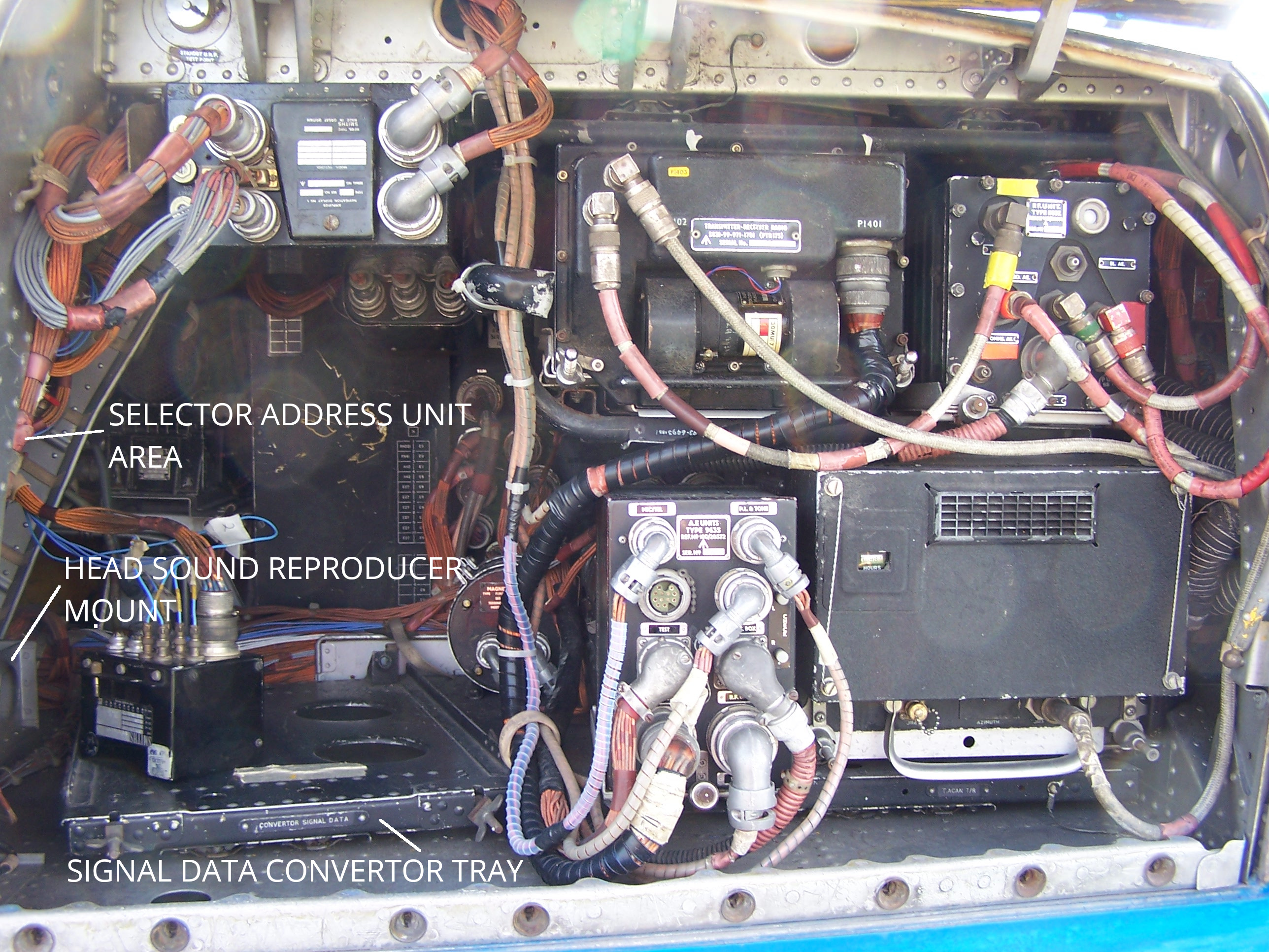
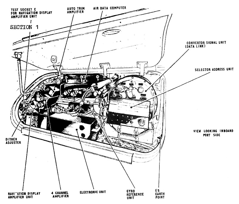
Data Link component locations system in the
port "elephant's ear" of T Mk.5, XS458 22-04-2006
Edited extract from
AP101B-1005-1B, Sect.8, Chap.1, A.L.66, Sept.75, Fig. 1
(T Mk.5) UHF VHF Intercom and Telebrief - Locations
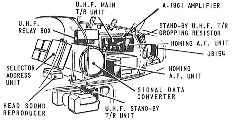
Edited extract from
B.A.C. Warton Lightning Airframe Course Notes, Phase A, Chap.4, Page.10 March.74
(F Mk.6) Main equipment bay panel 21P
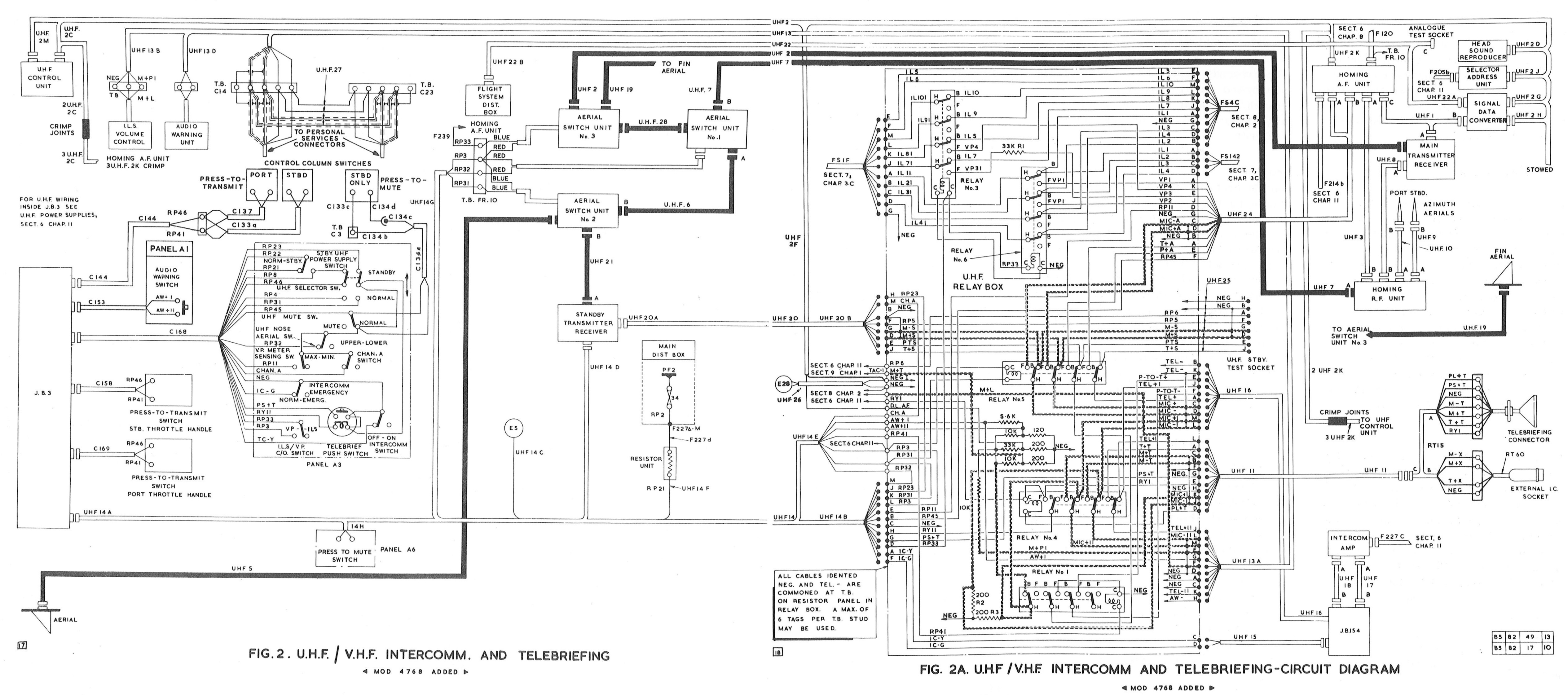
Edited extract from
AP101B-1005-1B, Sect.8, Chap.1, A.L.66, Sept.75, Fig. 2&2A
(T Mk.5) UHF VHF Intercom and Telebrief
PTR-177 T/R Unit
The PTR-177 T/R unit contains an R.F. Demodulator module; this is the only difference between the PTR-177 and PTR-175 which is fitted with an additional Guard receiver in place of the demodulator.
The PTR-177's demodulator module observes the received F.S.K. R.F. frequencies and turns this into a binary 1 or 0. The ground radar station would transmit on a chosen U.H.F. frequency, and using F.S.K. would modulate this frequency by +/- 20KHz.
Within the PTR-177 T/R unit, the R.F. Demodulator receives a signal from the PTR-177's second IF (Intermediate Frequency) stage, which is nominally 1.85 MHz, but +/- 20 KHz due to the F.S.K. modulation, this results in:
- 1.87 MHz = binary 0
- 1.85 MHz = binary 1
The demodulated binary (digital) signal is passed from the PTR-177 T/R unit to the Signal Data Converter for processing.
Two types of Data Link RF demodulator were available for the PTR-177: earlier valve design NSN 5821-99-913-4674 (shown below); and later transistorised version NSN 5821-99-948-8104.
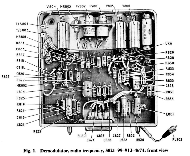
Extract from
AP116D-0113-6A, Sect.2, Chap.19, A.L.25, July.68, Fig. 1
Demodulator Radio Frequency 5821-99-913-4674, Rear
Signal Data Converter
Below is the only image I have found of one of the system units, a signal data converter on display at the 1961 SBAC exhinition. This image was taken from an article in Flight magazine about the exhibition.
Caption form image:
Below left, the airborne unit for the G.E.C. data link.
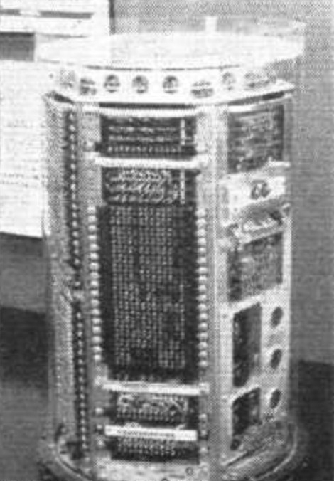
Extract from
Flight magazine 14 Sept. 1961, Page 428
Data link signal data converter on display at the SBAC exhibition
TRIAL DATES / WITHDRAWAL FROM SERVICE?
As with all things Data Link, information is sketchy.
The air speed indicator I have for this project shows witness marks of its command speed counter being removed, implying it was once fitted. This counter is installed in the lower left corner, plus there was an additional moving tape marked with a ring shape. Sadly the modification record plate does not include details or dates.
When Data Link was not in use in the Lightning, the PTR-177 T/R unit is replaced with the Plessey PTR-175 which provides the same communication facility, and contained a separate Guard channel receiver in place of the Data Link RF Demodulator module.
Dates
The T Mk.5 references are copies of the Vol.1, AP101B-1005-1B, Sect.8, Chap.1, AL66 from 1975, and AL76 from 1978, however the T5 (F3 andd F6) Lightning aircrew manual AP101B-1003, 5 and 6-15A, AL2 from 1982 states the Data Link was not used by this point. The radio repair manual AP116D-0113-6A, Sect.2 include the two types of demodulator is Chap. 19, A.L.25, in July 1968, and Chap 20, A.L.38, 1970.
EXPORT AIRCRAFT
I can only find references to the PTR-177 and Data Link system being installed in the RAF aircraft, not the export F Mk.53 or T Mk.55 (to non-NATO Saudi Arabia and Kuwait), which I'm sure is a reflection of the supporting ground infrastructure of Linesman being a UK system.
SIDE NOTES
Talking to ex-RAF personnel, the space in the main equipment bay where the anti-vibration tray sits for the Signal Data Converter unit (when not fitted) was sometimes used by aircrew for their kit bag. This I can believe, having repaired abused wiring harnesses in this area on XS458.
REFERENCES
T Mk.5 electrical "Vol. 1":
A.P.101B-1005-1B, Sect.8, Chap.1, A.L.66, Sept. 1975 - U.H.F./V.H.F., Intercommunication and Telebriefing
F Mk. 3, T Mk. 5 and F Mk. 6 aircrew manual:
A.P.101B-1003, 5 & 6A, Part 1, Chapter 13, A.L.2, Nov. 1984, Communications Equipment
T Mk. 5 wiring diagrams:
AP101B-1005-10, Sheet 55, A.L.3, Nov. 1981, V.H.F. / U.H.F. Intercommunication and Telebriefing
U.H.F Transmitters and Receivers (ARC. 52 and Derivatives) - Repair and Reconditioning Instructions:
AP116D-0113-6A, Part 2, Sect 2, Chap 19, A.L.25, July 1968, Demodulator, Radio Frequency 5821-99-913-4674
U.H.F Transmitters and Receivers (ARC. 52 and Derivatives) - Repair and Reconditioning Instructions:
AP116D-0113-6A, Part 2, Sect 2, Chap 20, A.L.38, July 1970, Demodulator, Radio Frequency 5821-99-948-8104
NATO Link 4 Specification:
SGM-0229-62, 16 April 1962, Link 4 Specification
Flight Magazine:
Flight, 14 Setpember 1961, Page 428
External Links
NATO Archives:
Notes and Standards for Data Link ↗
Federation of American Scientists:
Link 11 and Link 4 description ↗
The Association Of Royal Air Force Fighter Control Officers:
Article: Controlling the Lightning ↗
Radarpages:
Article: Linesman ↗
Wikipedia:
Tactical Data Link ↗
Link 4 ↗
Frequency Shift Keying ↗
Signal Identification Wiki:
Military Signals ↗
PPRuNe forum, Lightning and Data Link discussion:
Anyone remember Lightning DataLink? ↗