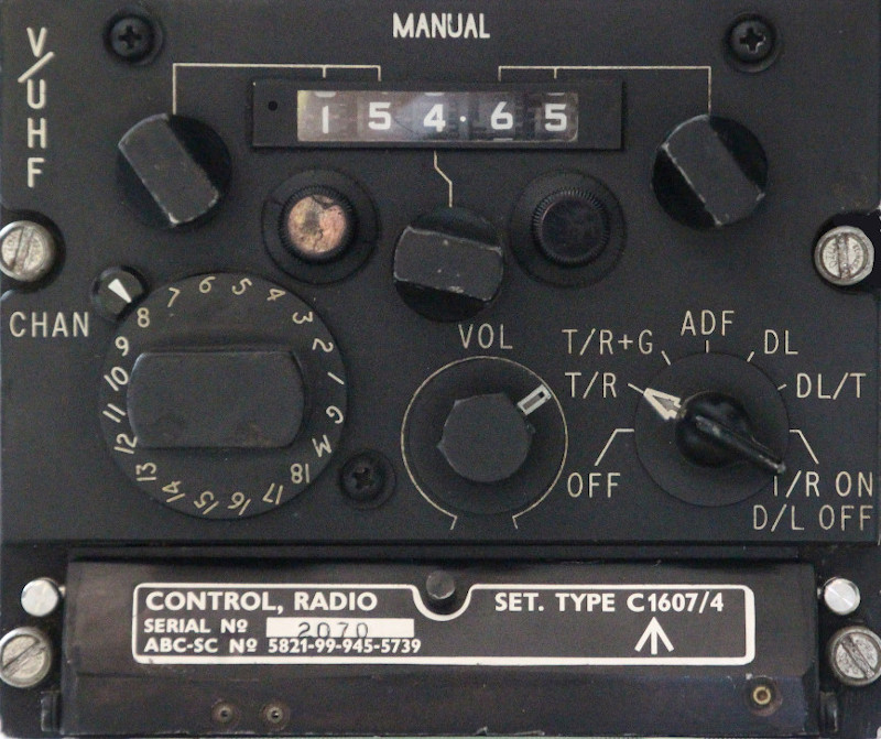
VHF / UHF RADIO CONTROL UNIT TYPE C1607/4
LEADING PARTICULARS
| Stores Ref. No.: | 10L/9455739 |
| NATO Stock No.: | 5821-99-945-5739 |
| Manufacturer: | Plessey |
| Attachment: | Dzus D5 Panel Line quarter turn fasteners |
| Connection: | Cannon KO3-21-30-SN |
| Installation: | A.R.I. 18168/2 (Mod. 4289 for Data Link, PTR-177 T/R Unit) |
| Systems: | VHF/UHF, Intercom and Telebriefing, Violet Picture UHF Homing / A.D.F. & Data link |
DESCRIPTION
Control unit for the PTR-175 or PTR-177 VHF / UHF communications radio.
It is capable of UHF / VHF tuning to 50kHz channel spacings either manually or by pre-programmed channel selection, setting modes for "Violet Picture" Automatic Direction Finding (ADF), Data Link (DL) or separate guard receiver (T/R+G).
A hidden switch round the back allows for configuration for use with a PTR-175 T/R unit (additional guard reciever), or PTR-177 T/R unit (data link).
| C1607/4 Mode Switch | PTR-175 T/R Unit Installed | PTR-177 T/R Unit Installed |
|---|---|---|
| OFF | Off | Off |
| T/R | Voice Transmit/Receive | Voice Transmit/Receive |
| T/R+G | Voice Transmit/Receive Additional Guard Receive | Voice Transmit/Receive |
| ADF | Voice Transmit/Receive Automatic Direction Finding ON | Voice Transmit/Receive Automatic Direction Finding ON |
| DL | N/A | Data Link Receive No Voice Transmit/Receive |
| DL/T | N/A | Data Link Test Facility No Voice Transmit/Receive |
SIMULATION
The plan is to pass the selected frequency to Flightgear, then somehow have Flightgear interface with a VOIP client such as Mumble to select 'rooms' / 'channels' according to the frequency selected.
The 50kHz spacings may prove to be slightly difficult in a modern simulator environment with airfields now using 8.33kHz channel spacings. A multiplayer scenario may need airfield frequencies to be set up at 50kHz spacings, or a cheat solution would be to use the preset channel drum to simply indicate to the computer the channel selected, and then have the computer switch to the accociated frequency of the more modern 8.33kHz spacings, meaning not using the manual settings.
As the unit also includes the main radio volume control, this is intended to be used too.
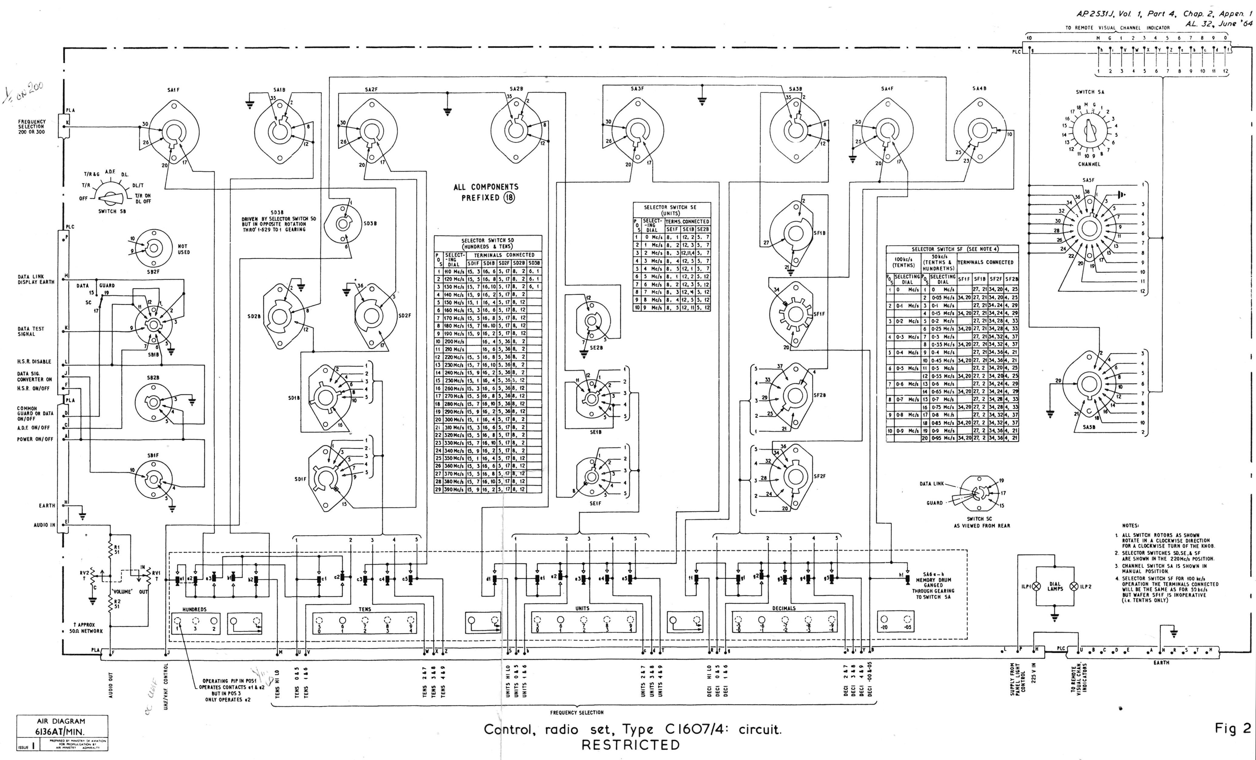
CIRCUIT DIAGRAM
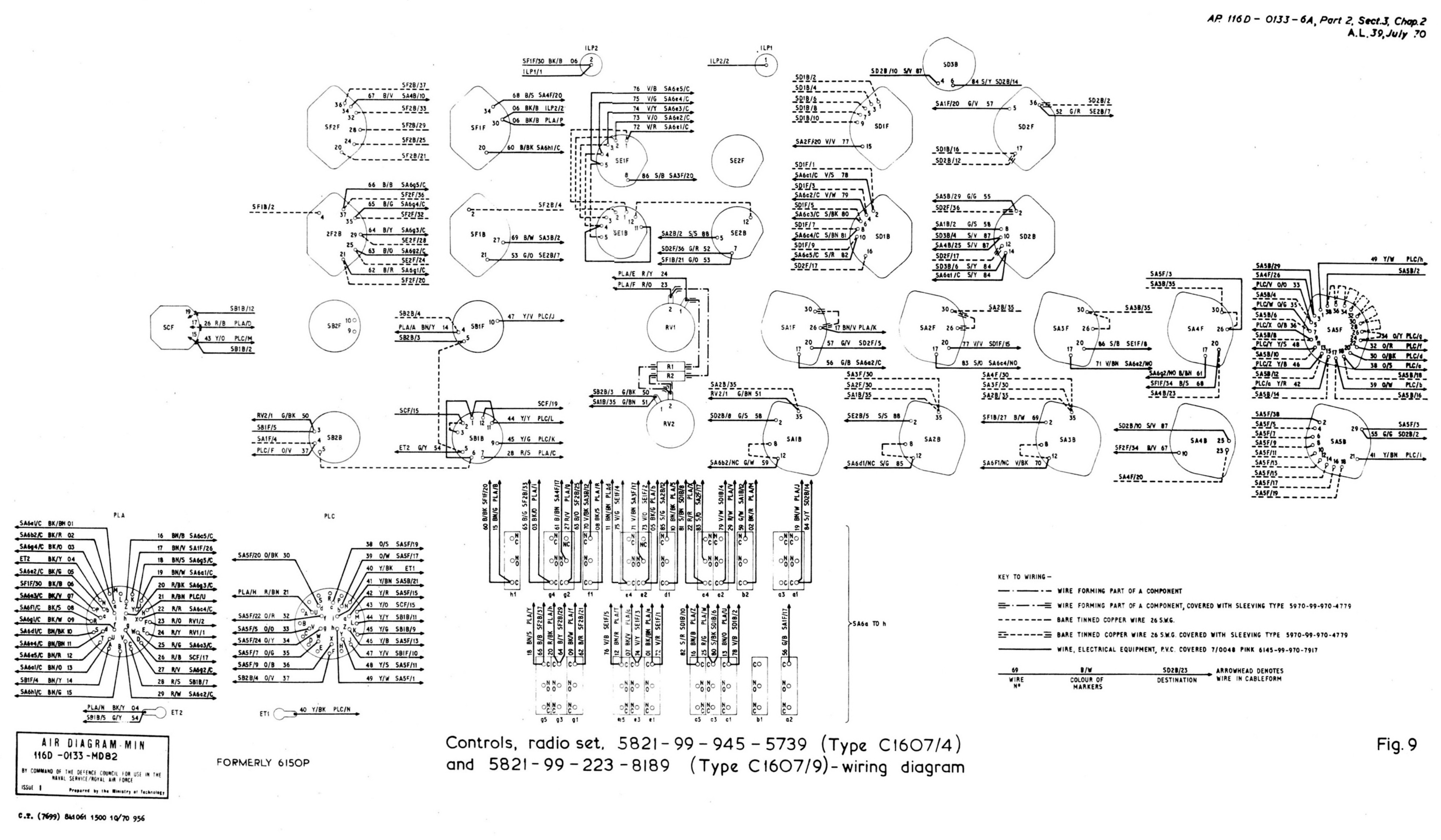
WIRING DIAGRAM
REFERENCES
Control unit general and technical information:
A.P.2531J, Vol. 1, Part 4, Chapter 2, Appendix 1, A.L.32, June 64 - Control, Radio Set, Type C1607/4
U.H.F Transmitters and Receivers (ARC. 52 and Derivatives) - Repair and Reconditioning Instructions:
AP116D-0113-6A, Part 2, Sect 3, Chap 2, A.L.39, July 1970, Control, Radio Set, Type C1607/4 and C1607/9
F Mk. 3, T Mk. 5 and F Mk. 6 aircrew manual:
A.P.101B-1003, 5 & 6A, Part 1, Chapter 13, A.L.2, Nov 84 - Paragraph 7
T Mk. 5 electrical "Vol. 1":
A.P.101B-1005-1B, Section 8, Chapter 1, A.L.66, Sept 75 - Paragraph 10
T Mk. 5 wiring diagrams:
AP101B-1005-10, Sheet 55, A.L.3, Nov 1981, VHF, UHF, Intercommunication and Telebriefing