PTR-175 Control Unit C1607/4 In Detail
This control unit sits in the aircraft cockpit panel, and connects to the radio system via an interconnecting box or an AF Unit depending on the installation. It controls the frequency of the PTR-175 Radio T/R Unit, mode of operation and the volume.
Operation
It offers the facility to manually set the T/R Unit transmit and receive frequency using the display and three smaller knobs. This is only possible with the Channel Selector set to 'M' (Manual). Rotary switches behind these knobs are routed to the T/R Unit when 'M' is selected on the Channel Selector.
18 (plus 'G', so really 19) preset frequencies are available via the Channel Selector. The 'G' channel should be left set to the Guard (distress) frequency, but is actually fully tunable as per the other 18 channels.
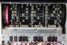
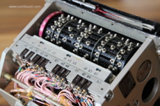
The preset frequencies are set by adjusting spring loaded studs along slots cut into a drum. The drum is rotated to the desired channel to allow adjustment of the studs using a special tool through a slot behind a hinged cover. The channel available for adjustment is identified by a red figure on the left. Once the studs have been slid into position, the Channel Selector is used to select the channel just set, this rotates the drum and aligns the studs just set with a row of microswitches in the rear of the Control Unit. The electrical signals of these microswitches are routed to the T/R Unit when the Channel Selector is not set to 'M'.
Images with the unit powered up and illuminated
A selection of images showing in detail how this controller looks in different light conditions and when illuminated and not. Illumination tested with Red and White light.
The lettering illuminates as the front panel is made of a laminated Perspex. It has a thick layer of perspex where the light from two bulbs shines through, then a thin white layer, topped by a thin black layer. The lettering is machined / etched into the black layer, exposing the white layer, which is fine for daytime use, but at night time, the bulbs are switched on and shine through the thin white layer, making the lettering stand out.
Please ignore the blu-tak holding the upper right 1/4 turn screw in place!
Please click on the images for larger view:
You can see how the red filters around the bulbs block a lot of light, the white light is much brighter. The bulbs used in the photos are all the same 28V 40mA type P bulb, but operated at 24Vdc due to available power supply at the time, so you could assume that naturally they would be a touch brighter. Power was applied between Pin P of the connector and the chassis for ground.
I'm not sure what installations would use white light, as most aircraft I've been involved with use red light. Perhaps the control tower, or field portable applications? If anyone knows, please drop me a line.
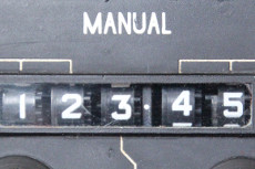
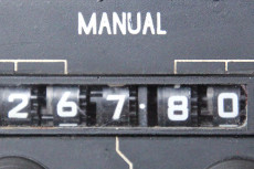
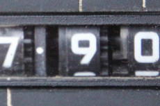
Manual character detail
These images have been published here to support FGUK aircraft 3D model projects.
Sounds
This video captures the sounds of the different controller switches / knobs.
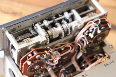
Inner switching / tuning mechanisms
The inner workings of the controller.. it's a clockwork beauty..
You can clearly see for manual tuning the rotary switches behind the display and tuning knobs, and for preset tuning, the slotted memory drum and the studs, and how they act upon the row of microswitches at the back.
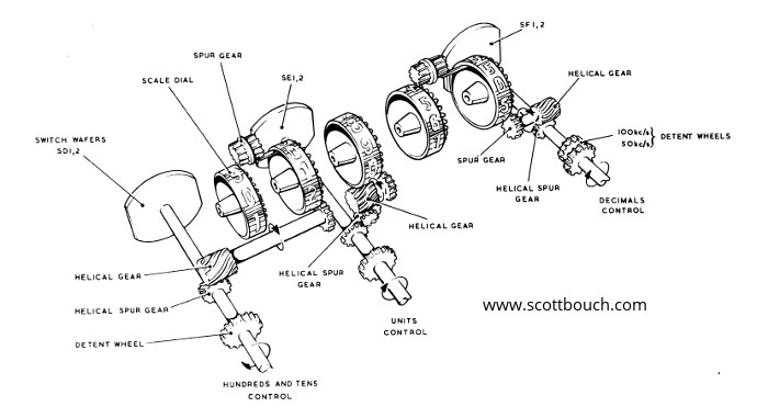
C1607/4 control unit manual switching mechanism diagram
