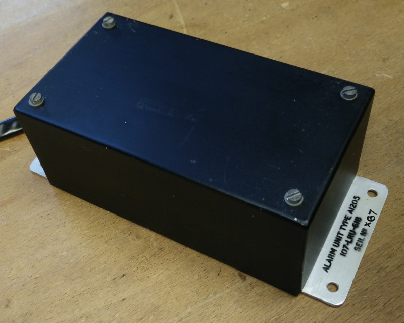
ALARM UNIT / AUDIO WARNING UNIT / ELECTRONIC FIRE BELL
TYPE A1205 / 107-LRU-61A / 107-LRU-61B
LEADING PARTICULARS
| Stores Ref. No's.: | 5CZ/5651, 5CZ/6479, 5CZ/4337673 |
| Manufacturer: | S.T.C. |
| Connection: | Flying Leads |
| Attachment: | 4BA screws |
| Systems: | Warning and Emergency & VHF/UHF, intercom and telebriefing |
DESCRIPTION
This unit provides an audio warning tone into the aircrew headsets, colloquially knows as "the clangers".
The tone is triggered by the warning system annunciating a new issue. It continues to produce the audio tone until the "C" cancel button is pressed. The tone is designed to resemble the rapid striking of a physical fire bell, where a base tone is pulsed (modulated) and "tails off" in between pulses to resemble the ringing of a bell, as per sample audio clip below:
Sample audio clip of warning tone
From T5 Lightning XS458 via the intercom system
Recorded October 2018 (Note 1)
The unit contains two transistorised multivibrator circuits; the first produces the base tone frequency, and the second modulates this to create the striking sound effect.
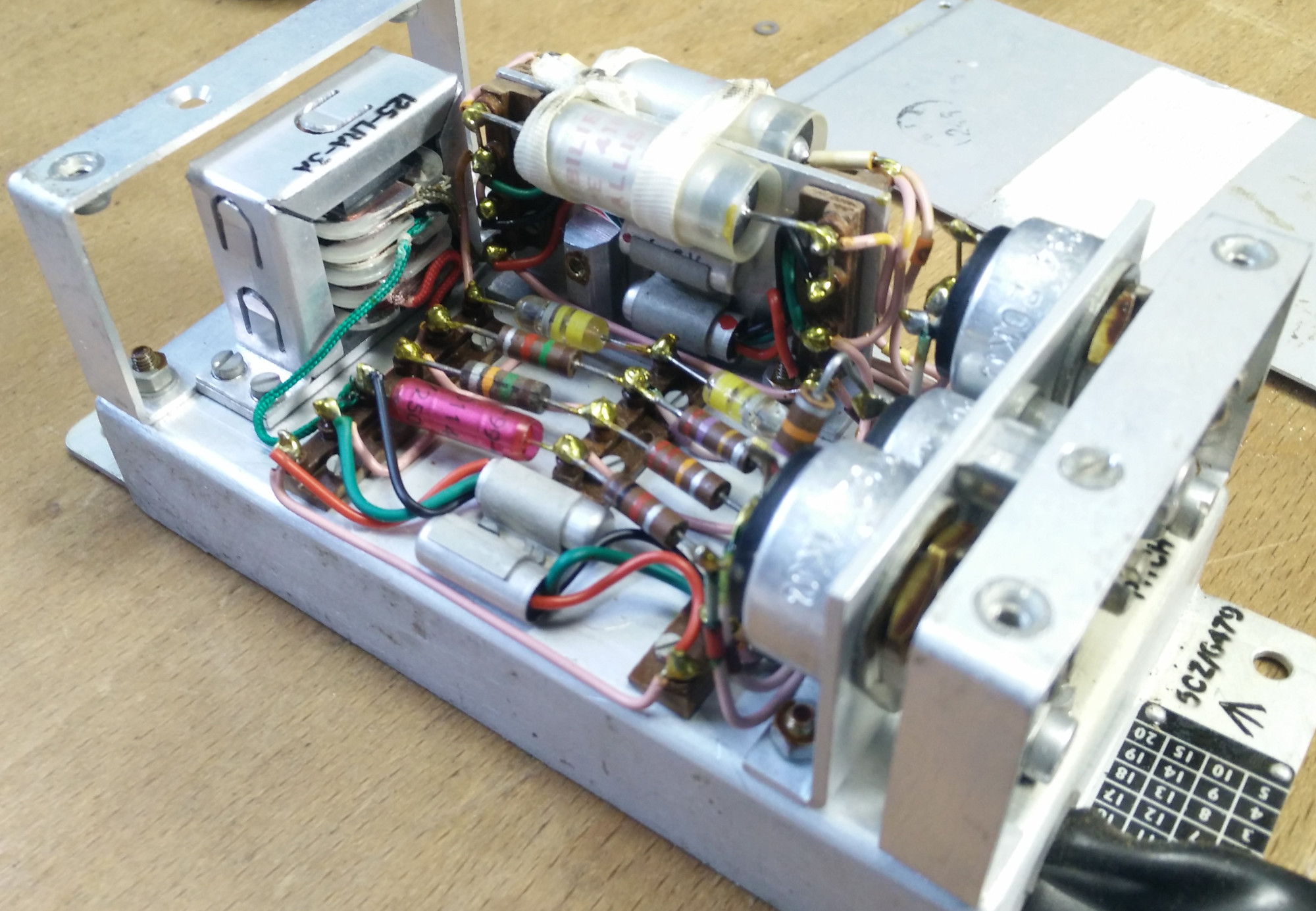
Alarm unit type A1205 5CZ/6479 internals
The fundamental frequency of the first multivibrator (base tone) is approximately 1 kHz, the second multivibrator is used to modulate the base tone at approximately 6 Hz.
A multivibrator is an oscillator that produces numerous harmonics above the fundamental frequency. The harmonics are useful to create a characteristic tone, this effect is further accentuated by a tuned circuit designed to resonate at the 3rd harmonic of the fundamental (approximately 3 kHz).
INSTALLATION
In the T Mk.5 & T Mk.55 Lightnings, this unit is located behind the port (pupil) ejection seat, just inboard of the flasher and excitation unit.
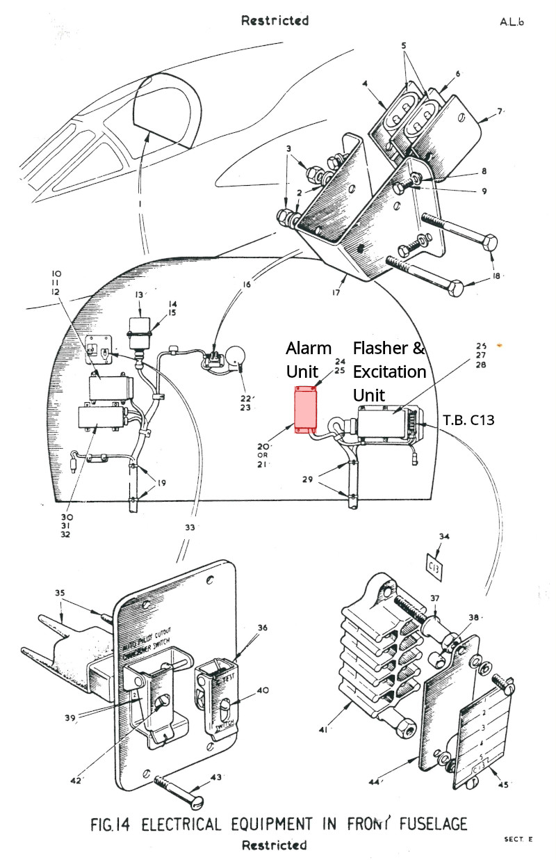
BAC 55 (SA-3) T55 IPC, Book 1, Section E, Fig 14
Alarm unit marked - item 20 or 21
Its flying leads are terminated to terminal block T.B C13 as shown below on the cockpit sloping rear bulkhead.
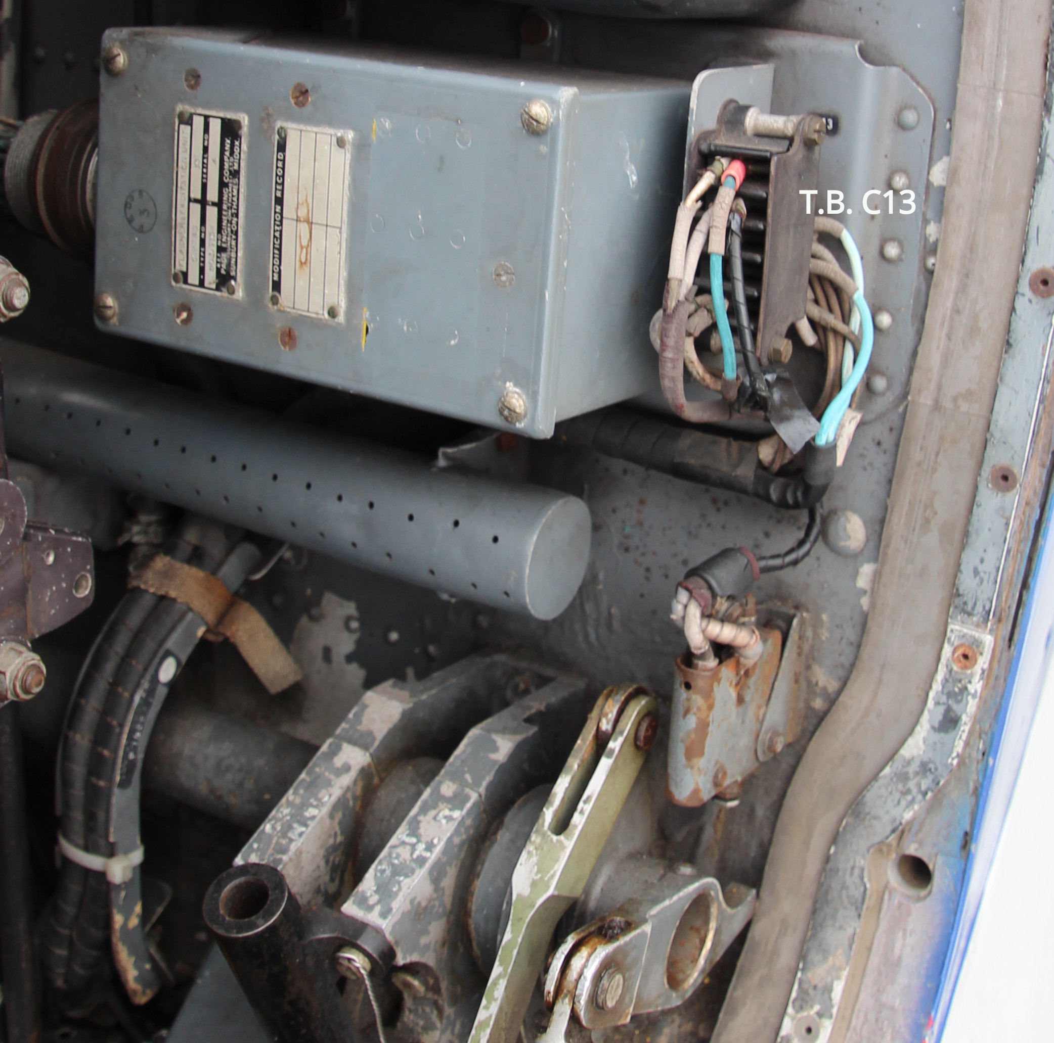
Ward Brooke terminal block T.B. C13,
XS458, cockpit rear bulkhead, port side, 07/10/2018
The three blue colour pren wires are from the alarm unit, the forward/left side is the AW+ (Tel+) connection and the spiral wrapped wire is the screen AW- (TEL-) connection. The other two to the rear/right are the power WK22 (28V+), and earth WK23N (28V-) connections.
TEST No. 1
I had a 'new old stock' alarm unit to try, this video is of an initial test connected to a type G flying helmet
The test revealed that the base frequency was lower than the expected 1 kHz, likely due to an issue in the first multivibrator circuit.
Note: In the video I state electrolytic capacitors. After closer examination, even though they looked like typical electolytics, they were actually metallised film capacitors.
RESTORATION
TESTING
Examining the circuit diagrams, two components stood out as likely candidates for causing this issue, C1 and C2, which with resistors R1, RV1 and R4 dictate the frequency of the first multivibrator circuit. An initial test involved de-soldering one leg of each 0.1 µF capacitor C1 and C2, and testing with a multimeter found them to have a capacitance in the region of 0.5 µF. In an RC network the larger the capacitance, the lower the resonant frequency, supporting the initial presumption.
Measuring in mid point between diodes MR1 and MR2; with the tone potentiometer RV1 at min, 340 Hz measured, and RV1 at max, 460 Hz measured - well below the 1 kHz noted in the manuals.
REPAIR
After discussion with other electronics repair enthusiasts of vintage-radio.net↗ it turns out that metallised film capacitors are known to be susceptible to moisture ingress, past their neoprene end seals, which can affect their capacitance. It was suggested that a suitable replacement of equivalent vintage would be a much more stable Mullard "Mustard" C296 polyester capacitors, and a member kindly donated a pair (dated 1967). I tested the replacement capacitors and found their capacitance to be almost exactly the required 0.1 µF, no degradation over the years.
Fitting the replacement capacitors required using a cotton bud with methylated spirits to clean off the original orange/golden shellac coating of the soldered joints to the terminal posts, which melted away with ease. The capacitors were tied down to an aluminium plate to support them during high 'G' flight manoeuvrers, this lashing required removing to free them off. The lashing was tied with granny knots.
TEST No. 2
This test, conducted after replacing C1 and C2, demonstrates the change in frequency caused by the old capacitors.
As can be seen in this video, the frequency is now easily adjusted between ~800 Hz and ~1 kHz, the repair worked nicely.
REFERENCES
Unit General and Technical Information:
AP4343E, Vol. 1, Sect. 18, Chap. 15, AL115, March 1958, Audio Warning Unit, S.T.C., Type A1205
AP113F-0629-13A6, AL1, Oct. 1969, Electronic Fire Bell, S.T.C., Type 107-LRU-61B
T Mk.5 electrical "Vol. 1":
A.P.101B-1005-1B, Sect.6, Chap.12, A.L.61, Nov. 1973 - Warning and Emergency Services - paragraph 8
T Mk. 5 Wiring Diagrams:
AP101B-1005-10, Sheet 83, A.L.3, Nov 1981, Warning and Emergency - Standard Warning System
AP101B-1005-10, Sheet 55, A.L.3, Nov 1981, VHF, UHF, Intercommunication and Telebriefing
T Mk. 55 Illustrated Parts Catalogue:
BAC 55 (SA-3) T55 IPC, Book 1, Section E, Fig 14
Air Cadet Training Handbook - General Service Training:
ACP31, Book 1, Section 5, Chapter 3, Page 30 AL4 September 1978, Knots - Fig 21H
NOTES
NOTE 1
XS458 audio sample recorded October 2018 under the following conditions: Aircraft on battery power and all other electrical equipment turned off to reduce electrical noise; 1 x type G helmet connected to provide a load to Tel circuit; mask microphone turned off to exclude external audio noise; A1961M transistorised intercom amplifier in use to avoid rotary transformer of A1961 valve based amplifier.
An adaptor to reduce headphone voltage level to microphone level as used (containing decoupling capacitors, 1:1 isolating transformer and resistor network), Canon EOS 650D DSLR camera used to record resultant sound via microphone input as video. Audacity on Linux used to extract audio clip.
NOMENCLATURE
Confusingly this unit has two names, a few reference numbers, part numbers, and confusion over the meaning of the A and B versions being due to the use of different transistors or capacitors. I have tried to make some sense of the information available in the table below:
| Reference Source | Stores Ref. No. | Type | Name | Also Known As | Details |
|---|---|---|---|---|---|
| Printed on physical unit | 5CZ/6479 | A1205 | Alarm Unit | 107-LRU/61B | N/A |
| AP4343E, 1958 | 5CZ/5651 | A1205 | Audio Warning Unit, S.T.C. | Electronic Fire Bell 107-LRU/61A | A/B denotes transistor types (unspecified) |
| AP4343E, 1958 | 5CZ/5651 | A1205 | Audio Warning Unit, S.T.C. | Electronic Fire Bell 107-LRU/61B | A/B denotes transistor types (unspecified) |
| AP113F-0629-13A6, 1969 | 5CZ/5651 | 107-LRU/61A | Electronic Fire Bell, S.T.C. | Part No. A1205 | A/B denotes capacitor type. C1 & C2 "A" NSN: 0631-5910-99-011-9827 |
| AP113F-0629-13A6, 1969 | 5CZ/6479 | 107-LRU/61B | Electronic Fire Bell, S.T.C. | Part No. A1205 | A/B denotes capacitor type. C1 & C2 "B" NSN: 0631-5910-99-011-5560 |
| A.P.101B-1005-1B, 1973 | N/A | A1205 | Audio Warning Unit | N/A | N/A |
| AP101B-1005-10, Sheet 83, 1981 | N/A | N/A | Audio Warning Unit | N/A | N/A |
| AP101B-1005-10, Sheet 55, 1981 | N/A | N/A | Audio Warning Unit | N/A | N/A |
| AirSam catalogue | 5CZ/5651 5CZ/6479 | A1205 | Warning Unit | 5CZ/6350-99-4337673 5CZ/4337673 | N/A |
| iso-group.com, 2023↗ | N/A | N/A | Warning Unit, Audio | NSN 6350-99-433-7673 | N/A |