
AUDIO WARNING MUTING SWITCH TYPE C.1006/A/21
LEADING PARTICULARS
| Stores Ref. No.: | 5CW/4400375 |
| Manufacturer: | Page |
| Attachment: | Nut |
| Connection: | Solder tags |
| Systems: | Warning and Emergency & VHF/UHF, Intercom and Telebriefing |
DESCRIPTION
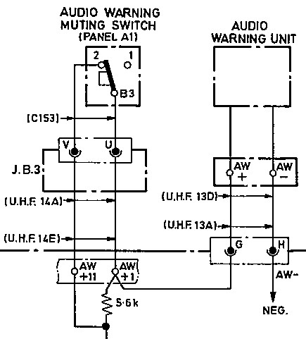
Labelled on panel A1 as "AUDIO MUTE" this switch actually reduces the volume of the audible warning by pulling the button face out. The audio warning tone (known as "the clangers") is generated by the audio warning unit, and is heard in the aircrew headsets.
It is an illuminated switch, indicating when volume reduction is active, however I am still to find the circuit diagram of the illumination wiring.
This switch under normal conditions connects the output of the audio warning unit to the audio mixing circuit via a normally closed contact, but when muting is active and the contacts open, a 5k6Ω resistor is introduced in series with the audio warning signal (within the UHF relay box) to reduce the volume.
SIMULATION
The audio warning volume can be set within a Nasal script in the FGUK EE Lightning model, so this switch will control the volume to 100% and a lower % when active.
CIRCUIT DIAGRAM
Extract from AP101B-1005-10, Sheet 55, Fig 1, A.L.3, Nov 1981:
REFERENCES
T Mk. 5 wiring diagrams:
AP101B-1005-10, Sheet 55, A.L.3, Nov 1981, VHF, UHF, Intercommunication and Telebriefing