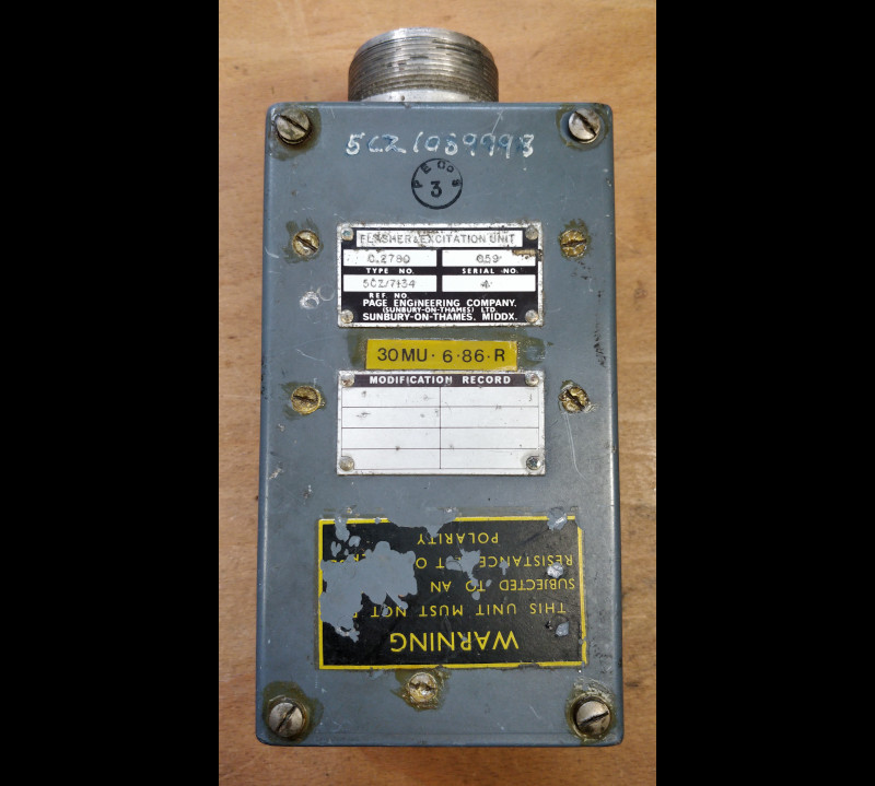
FLASHER & EXCITATION UNIT
TYPE C.2780
LEADING PARTICULARS
| Stores Ref. No.: | 5CZ/7134 | 5CZ/1089998 |
| Manufacturer: | Page Engineering |
| Manufacturer P/N: | C.2780 |
| Attachment: | 28D/1010658 | A25/1B | Bolt, 4BA, hex head | Qty: 4 |
| Attachment: | 28W/9419401 | SP10/B | Washer, 4BA, plain | Qty: 4 |
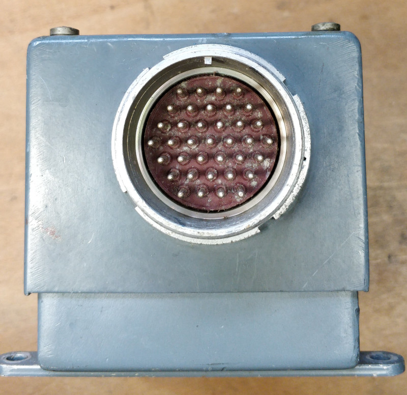
| Connection: | UK-AN / MIL-C-5015, 28-21P, 37 way |
| System: | Warning and Emergency Services |
DESCRIPTION
This unit forms an important part of the functionality of the standard warning system. In essence it is a hardwired logic control unit that provides some functions associated with warnings based on aircraft sensors/switches.
When a hazardous condition arises, a switch contact in the airframe closes, illuminating a pair of lamps in one of the warning panel caption windows. This warning could be a high/low pressure, temperature, an electrical issue, or other hazardous condition. The warning system observes conditions of many other systems.
The flasher and excitation unit only interfaces to the standard warning panel (SWP), which annunciates the warnings classed as critical. It electrically monitors the power to the warning caption lamps, and upon illumination, the flasher and excitation unit is responsible for flashing the attention getter lamps, and sounding the audio warning alarm. It latches in this state until the SWP "C" cancel button is pressed, or the warning clears naturally.
An SWP muting function is also provided for ground use, as during prolonged periods of servicing or systems testing the SWP lamps may overheat. This is carried out by the flasher and excitation unit by removing the earth connection to all SWP lamps apart from the fire warning lamps, which are permanently active. A further benefit of the SWP muting function is to mute the audio warning alarm, meaning the intercom can be used by ground crew / technicians working on the aircraft with no nuisance audio alarm.
INSTALLATION
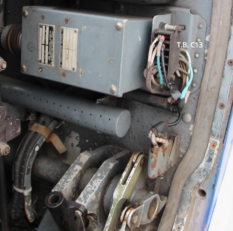
In the T Mk.5 & T Mk.55 Lightnings, this unit is located behind the port (pupil) ejection seat.
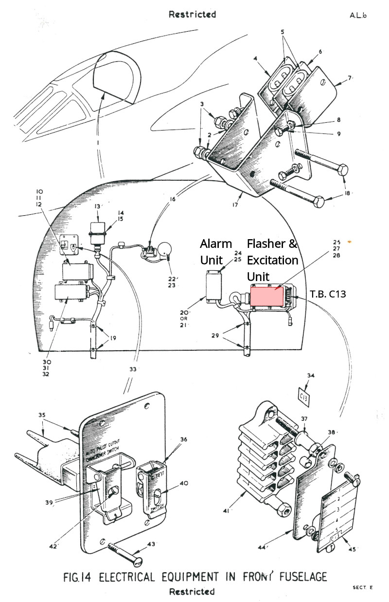
BAC 55 (SA-3) T55 IPC, Book 1, Section E, Fig 14
Alarm unit marked - item 20 or 21
Shown below on the cockpit sloping rear bulkhead, next to terminal block T.B. C13, its connector just behind the port ejection seat main rails.
FUNCTIONS
The flasher and excitation unit is responsible for the following functions:
- Latching and resetting the lamps of the standard warning panel (SWP).
- Triggering the audio warning alarm.
- Flashing the "attention-getter" warning indicator lamps and the SWP "C" button lamp.
- SWP muting function.
CONSTRUCTION
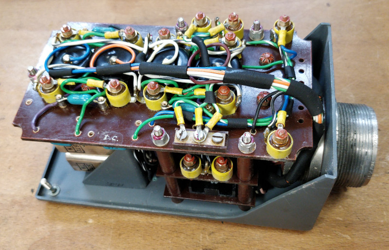
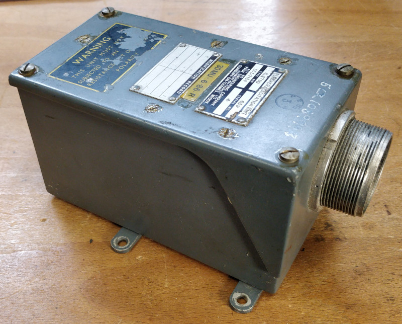
The enclosure is a two-part welded aluminium box, with all circuits and connector mounted to the top half of the enclosure. Mounting bars are riveted to the bottom half, no electronic components are mounted to the bottom half.
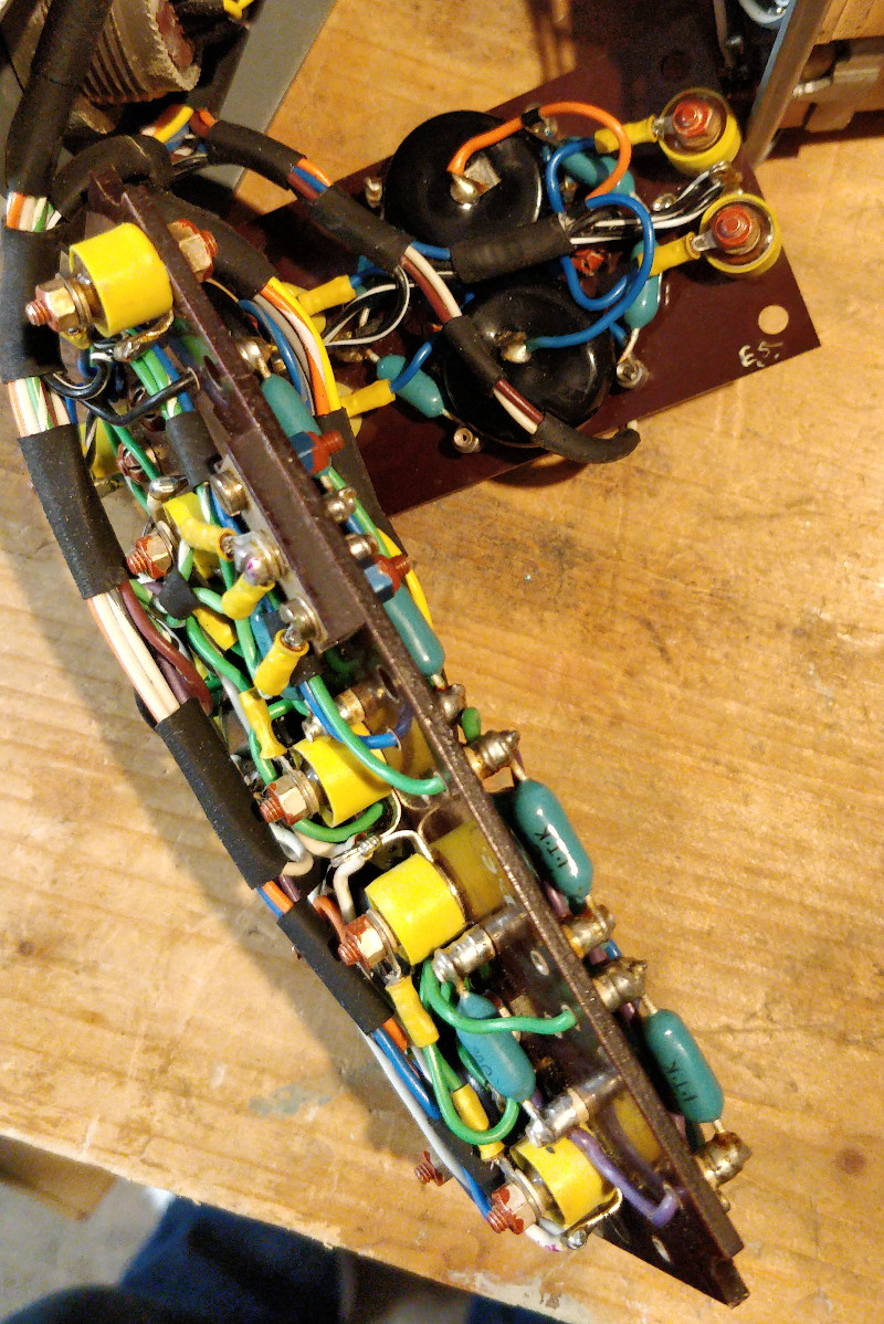
Internally, the circuits are formed by discreet components: diodes, capacitors and resistors mounted to SRBP (Synthetic Resin Bonded Paper) boards (such as Paxilon or Tufnol trade names), plus two types of relay.
LATCHING LOGIC
The inputs to the unit come directly from the lamps of the standard warning panel, SWP. The circuits are spread over two SRBP boards for sensing the signals from the SWP captions, diodes and capacitors are bolted through the board, while resistors are terminal post mounted.
Capacitors and a resistors are configured as differentiator circuits↗, producing short positive pulse signals when a warning lamp illuminates, and negative when it extinguishes.
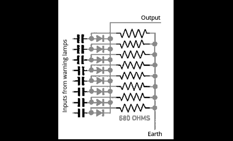
Flasher & Excitation Unit - differentiator circuit
The differentiator capacitors are marked with the NSN: 5910-99-012-0137, in A.P.101B-1005-1B, Sect.6, Chap.12, A.L.61, Nov. 1973 they are shown as 50 MF, which is translated to 50 μF. Looking them up here↗, here↗, and here↗ reveals they are Plessey Castanet Tantalum Electrolytic A50.70, 50 μF, 70 V rated. Plessey part No. 402/1/50001/001, Type A4BA, Tantalum anode, Tantalum Pentoxide dielectric, Silver cathode.
The resistors are made by Paintion.
A diode OR logic gate passes any of these positive pulse signals to the high speed relays, and blocks the negative pulses. The diodes prevent other lamps from flashing when a warning lamp is illuminated, and also stops the other capacitively coupled lamps loading the signal, so all current from the pulse is available to the high speed relay coil.
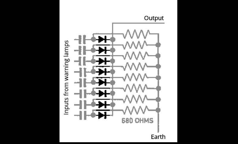
Flasher & Excitation Unit - diode OR gate circuit
The diodes are made by AEI, germanium type GJ4M.
The pulse energises one coil of a dual coil high speed relay, briefly energising it and closing its normally-open contacts.
One set of contacts connects a second coil to power derived from the SWP "C" button contacts, which in turn is supplied by the output of another diode 'or' gate within the SWP, again fed by the warning lamps.
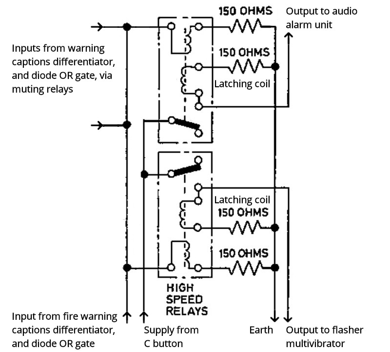
Flasher & Excitation Unit - high speed relay circuit
This means that the high speed relays stay energised (self-latched) while a lamp is illuminated, and will only de-energise if the lamp goes out, or if the "C" button is pressed, breaking the circuit. Pressing the "C" button does not extinguish the Warning lamp, but only de-energises the high speed relays. The warning lamps are directly controlled by the external switches of the aircraft systems.
The remaining contacts of the high speed relays are used to control the audio warning, and also the attention-getter warning indicator lamps, via a multivibrator circuit to produce the flashing effect.
The concept of the pulses created by the differentiator is to allow subsequent warning annunciations to trigger the attention-getters and audio warning after previously annunciated warnings have been cancelled.
The double coil high-speed relays are NSN: 5945-99-053-0037.
FLASHER MULTIVIBRATOR
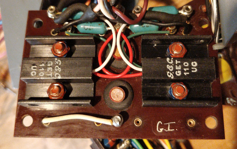
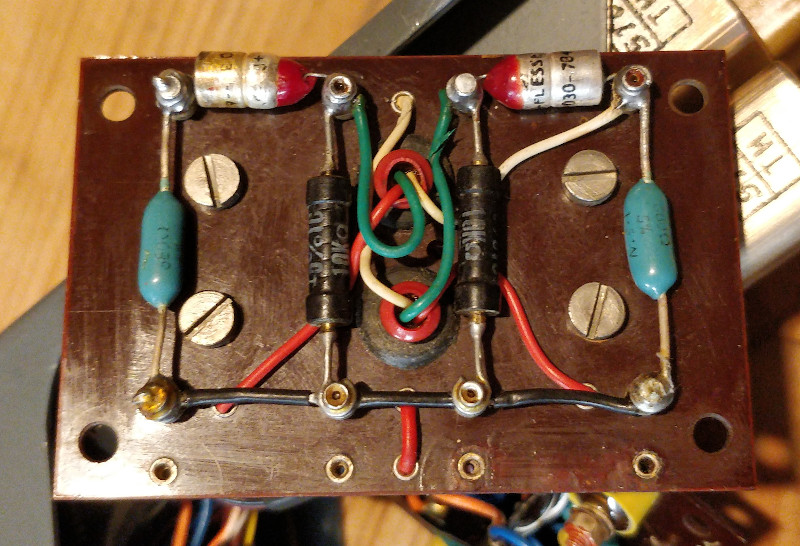
The multivibrator circuit is mounted on both sides of a small separate SRBP board. The circular GET111 transistors are mounted through rubber grommets, while the larger GET110 transistors are screwed to the board, all other components are post mounted.
The multivibrator capacitors are marked as Plessey E3030 type, in A.P.101B-1005-1B, Sect.6, Chap.12, A.L.61, Nov. 1973 they are shown as E30-30 with a hyphen. They are axial lead, and measure 30 μF, no further information can be found, but they are assumed to be tantalum capacitors.
The transistors are made by GEC, type GET111 perform the square wave switching, while GET110 transistors drive the current used by the lamps.
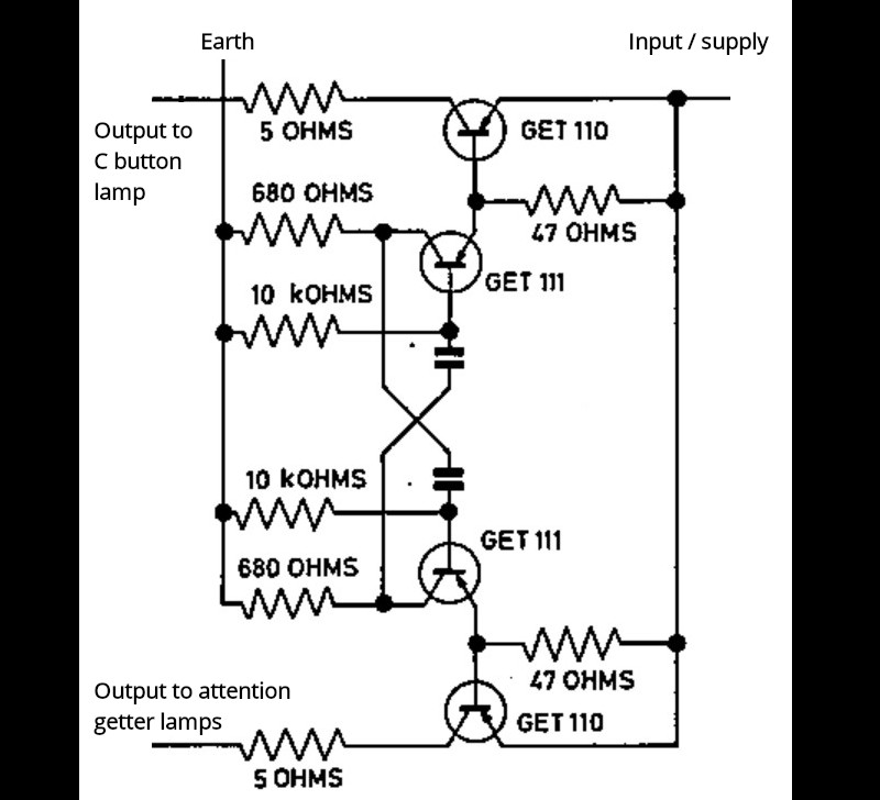
Flasher & Excitation Unit - flasher multivibrator circuit
SWP MUTE
SWP Mute is activated automatically to save nuisance alarms when the engine master switch on panel A5 is off, meaning the SWP (non-fire) warnings are only active when one or both engines are running.
There is one exception to this logic: upon switching on the battery master switch or applying external power. As the high speed relays are quicker to react than the muting relays, switching the power on to a Lightning always starts the flasher and audio alarm in the first instance, even though mute is active via the engine master switch. Once the "C" button is pressed, normal mute mode is resumed.
SWP Mute can also be manually activated by pulling out the "M" button of the SWP. This is intended to be used during long periods of ground testing work, to save the lamps overheating the panel.
Mute mode energises two muting relays. One contact disconnects the common earth connection of the non-fire SWP warning lamps, so they cannot illuminate when warning signals are active. Another contact from the muting relays interrupts power to the flasher multivibrator circuit, disabling the attention getter warning indicators, and also disables the audio warning unit.
While the "M" button is pulled out and mute is active, a lamp in the button illuminates to remind ground crew and aircrew to push it back in. The fire warning lamps are unaffected by muting.
The muting relays are made by STC, Part No.: 4184GD, NSN: 5945-99-053-0453.
SIMULATION
Examining this unit has been useful for establishing the exact logic of the system to aid the programming of functions of this unit in the Lightning model for Flightgear.
But for fun, I will use the unit as it would be used in the aircraft to flash the attention-getter lamps and provide the latching logic of the standard warning panel (SWP), instead of using the software logic. This will provide the clicks of the relays for added realism.
WANTED
This unit requires a 37 way connector
REFERENCES
F Mk. 3, T Mk. 5 and F Mk. 6 aircrew manual:
A.P.101B-1003, 5 & 6A, Part 1, Chapter 9, A.L.2, Nov. 1984, Warning Systems and Lighting
T Mk.5 electrical "Vol. 1":
A.P.101B-1005-1B, Sect.6, Chap.12, A.L.61, Nov. 1973 - Warning and Emergency Services
T Mk. 5 wiring diagrams "Vol. 10":
AP101B-1005-10, Sheet 30, A.L.3, Nov 1981, Engine Services - No.2 Engine Starting And Control
AP101B-1005-10, Sheet 36, A.L.3, Nov. 1981, Lighting - Fig 1 Cabin Lighting - Port
AP101B-1005-10, Sheet 37, A.L.3, Nov. 1981, Lighting - Fig 2 Cabin Lighting - Starboard
AP101B-1005-10, Sheet 40, A.L.3, Nov. 1981, Generator System - Fig 1 DC Power Supplies
AP101B-1005-10, Sheet 41, A.L.3, Nov. 1981, Generator System - Fig 1A DC Power Supplies
AP101B-1005-10, Sheet 55, A.L.3, Nov 1981, VHF, UHF, Intercommunication and Telebriefing
AP101B-1005-10, Sheet 83, A.L.3, Nov 1981, Warning and Emergency - Standard Warning System
AP101B-1005-10, Sheet 84, A.L.3, Nov 1981, Warning and Emergency - Auxiliary Warning System
AP101B-1005-10, Sheet 85, A.L.3, Nov 1981, Warning and Emergency - Fire Protection System
