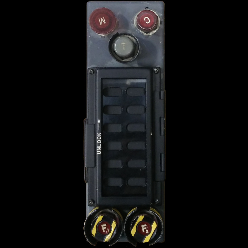
STANDARD WARNING PANEL INDICATOR UNIT
TYPE D.8700
LEADING PARTICULARS
| Stores Ref. No.: | 5CZ/8480 |
| Manufacturer: | Page |
| Manufacturer P/N: | D.8700 |
| Attachment: | 28D/9138768 | A25/1/2C | Bolt, 2BA, hex head | Qty: 4 |
| Connections: | 2x UK-AN / MIL-C-5015, 24-28P, 24 way |
| System: | Warning and Emergency Services |
DESCRIPTION
This indicator unit is part of the warning and emergency services system. Its key function is to display warnings upon issues or faults occurring, deemed as "critical".
The S.W.P. (Standard Warning Panel) displays illuminated red captions upon a critical event due to an issue or fault arising. When a caption illuminates, the audible warning begins to sound in the aircrew headsets, the attention getter lamps and "C" button on this panel begin to flash. This state is held until the "C" (cancel) button is pressed, acknowledging the event.
The logic of the warning system, such as latching/unlatching lamps and triggering of the audible warning is carried out by the flasher & excitation unit.
| Switch | Title | Description |
|---|---|---|
| "M" | Mute audible warning | Pull for mute, illuminates when muted |
| "C" | Warning annunciation cancel | stops attention getters flashing and audible warning |
| "T" | Indicator lamp test | Press to test all lamps, also sets off attention getters and audible warning |
| "F1" | No.1 engine fire warning | Indicates fire, and extinguishant release button |
| "F2" | No.2 engine fire warning | Indicates fire, and extinguishant release button |
The "M" mute button fitted to this unit is provided only for use while carrying out ground maintenance and testing of aircraft systems. When active most of the lamps of the SWP are disabled, the documentation states that this is to save the panel overheating due to pronged periods of lamp illumination. It also mutes the audible warning, which would be useful to technicians if the intercom system is being used to facilitate communications. It illuminates red when active, to warn a pilot to cancel the mute (push the button back in) when flying.
The indicators and buttons associated with the fire detection system cannot be de-activated by the "M" mute button.

S.W.P. F1 and F2 fire warning buttons
Summary of the standard warning panel captions:
| Caption | Warning Description |
|---|---|
| OXY 1 | Oxygen pressure low (pupil) |
| OXY 2 | Oxygen pressure low (instructor) |
| GEN | Generator failure |
| HYD | Hydraulic failure of both systems |
| TRIM | Auto trim circuit failure |
| CPR | Cabin pressure failure |
| RHT 1 | No. 1 jet pipe reheat area fire |
| RHT 2 | No. 2 jet pipe reheat area fire |
| FIRE 1 | No. 1 engine bay fire |
| FIRE 2 | No. 2 engine bay fire |
The unit being used by this project was originally fitted to XS417, now resident at Newark Air Museum, coincidentally where I display at CockpitFest each year, see unserviceable equipment label (MOD form 731) written in 1986. Also coincidentally, XS417 was the T Mk.5 photographed for the introduction of the Vol.1 AP's, it is likely that this very SWP unit was in the cockpit when this image below was taken. Even more coincidentally, I displayed this panel at Newark Air Museum in June 2024, within weeks of the 60th anniversary of XS417's first flight. And to add a bit more coincidence, XS417 was the first productoin T Mk.5 to fly, after two converted T Mk.4 prototypes.

XS417 from the 'Vol. 1' manuals
REPAIRS
MISSING GLASS
The original red glass plate was missing from the window. This is coated with a layer of black paint, with the caption lettering not painted, allowing the light through the lettering.
A piece of red perspex was found and cut to size to replace the glass.

SWP new caption sticker
A sticker was designed to replicate the layer of black paint, using the Pantograph Pro typeface font. A friend with a Cricut sticker cutting machine very kindly produced the sticker for me and helped to install it.
FAILED 'OR' GATE DIODE
During initial testing of the unit, an internal diode of the OR gate failed, leading to the "OXY 1" caption illuminating when other captions were illuminated. The diode for this caption had failed and had effectively become a resistor. The panel had not had power applied for nearly 40 years, but this has shown that these early silicon diodes suffer with age, I expect more to fail with further testing and use.

SWP OR gate diodes
I repaied this fault by adding a modern 1N4001 diode, and displayed the system at cockpitFest 2024 where it performed flawlwssly all weekend.

SWP OR gate diodes, modern 1N4001 indicated
However, a week after CockpitFest, another diode failed, this time "RHT 2".
STICKY BUTTON
Button F1 has a tendency to stick once pressed.
SIMULATION
This unit mainly consists of switches and lamps, all of which can be connected to without any modification.
I fabricated some connectors with help from Koos Bouwknegt, VintageAvionics.nl↗ which made it possible to apply power without causing any damage.

S.W.P. home made connectors
Experiment No. 1
The initial testing of the SWP was carried out in conjunction with the flasher & excitation unit. Connectors were fabricated for the SWP, and temporary connections made to the flasher and excitation unit. The connections made are as per the aircraft wiring diagrams.
Experiment No. 2
Action of adding of a second warning circuit, once the alarm from the first warning is cancelled, the second warning can trigger the alarm again. Also added the audio alarm unit to give a better feel of what it's really like.
Experiment No. 3
This video demonstrates the action of either turning on the battery master switch or applying external DC power to a Lightning. The first thing anyone does when powering up a Lightning is press the "C" button for the reason given here:
WANTED
This unit is fitted with two UK-AN / MIL-C-5015, 24-28, 24 way fixed plugs. Plug 1 has standard orientation, while plug 2 is in position Z at 280° rotation.

S.W.P. connectors
I'd really like to find the following UK-AN free unit sockets to connect to this unit, or equivalent MIL-C-5015, or MS-3102 series free unit sockets:
The required connectors are shell size 24 and contact layout 28, and having female contacts are sockets, making a general type of 24-28-S as per this drawing.
UK-AN free unit socket part numbers:
Socket 1: UK-AN-9100-24-28-S
Socket 2: UK-AN-9100-24-28-S-Z
If you think you can help out, please do get in touch.
REFERENCES
F Mk. 3, T Mk. 5 and F Mk. 6 aircrew manual:
A.P.101B-1003, 5 & 6A, Part 1, Chapter 9, A.L.2, Nov. 1984, Warning Systems and Lighting
T Mk.5 electrical "Vol. 1":
A.P.101B-1005-1B, Sect.6, Chap.12, A.L.61, Nov. 1973 - Warning and Emergency Services
T Mk. 5 wiring diagrams "Vol. 10":
AP101B-1005-10, Sheet 30, A.L.3, Nov 1981, Engine Services - No.2 Engine Starting And Control
AP101B-1005-10, Sheet 36, A.L.3, Nov. 1981, Lighting - Fig 1 Cabin Lighting - Port
AP101B-1005-10, Sheet 37, A.L.3, Nov. 1981, Lighting - Fig 2 Cabin Lighting - Starboard
AP101B-1005-10, Sheet 40, A.L.3, Nov. 1981, Generator System - Fig 1 DC Power Supplies
AP101B-1005-10, Sheet 41, A.L.3, Nov. 1981, Generator System - Fig 1A DC Power Supplies
AP101B-1005-10, Sheet 55, A.L.3, Nov 1981, VHF, UHF, Intercommunication and Telebriefing
AP101B-1005-10, Sheet 83, A.L.3, Nov 1981, Warning and Emergency - Standard Warning System
AP101B-1005-10, Sheet 84, A.L.3, Nov 1981, Warning and Emergency - Auxiliary Warning System
AP101B-1005-10, Sheet 85, A.L.3, Nov 1981, Warning and Emergency - Fire Protection System